
Electro-Permanent Magnets (EPM) vs. Electromagnets: The 2026 Engineering Guide to Fail-Safe Clamping, Energy TCO, and Precision Workholding
Compare electro-permanent magnets vs electromagnets: power-loss limits, thermal drift and 5-year TCO. Use the RFQ checklist to request an application review.
One-Line Decision Summary: Consider electro-permanent magnets (EPM) for long holding periods and precision workholding where avoiding continuous coil heating matters. Consider electromagnets for controllable force or a purpose-designed scrap-handling system. EPM retains its magnetic state during loss of supply, but this does not make a complete lifting or machining operation fail-safe against every fault.
Need technical guidance? Request an application review with your material grade, workpiece dimensions, working gap and duty cycle. Compare holding electromagnets, lifting electromagnets and custom magnetic assemblies.
Published / Reviewed: 2026-10-28. Scope: Global, English-language selection guidance for procurement teams, tooling engineers and automation integrators. European and UK safety references are regional context; applicable requirements depend on the installation jurisdiction and equipment category.
Evidence and limits: This is a desk-based engineering comparison with reproducible, hypothetical calculations. It contains no first-party pull tests, thermal measurements or customer cost records. Supplier-specific ratings and acceptance tests are required before a purchase or lift is approved. Review again by October 2027, or sooner if the application, supplier documentation or applicable requirements change.
Quick Navigation
- 1. Executive Summary: The Workholding & Lifting Dilemma
- 2. The Physics: Dual-Magnet Flux Steering vs. Continuous Ampere-Turns
- 3. Visual Architecture: Internal Flux Paths in Clamped vs. Released States (SVG)
- 4. Safety & Blackout Integrity: EN 13155 and Battery Backup Realities
- 5. Thermal Drift & Machining Accuracy: The Hidden Cost of Joule Heating
- 6. Demagnetization & Clean Release: Eliminating the Residual Magnetism Dilemma
- 7. Financial TCO & Energy Audit: 5-Year Lifecycle Cost Modeling
- 8. Comprehensive Engineering Specification Matrix
- 9. Workpiece Metallurgy, Air Gaps & Penetration Depth Guidelines
- 10. Pre-PO Specification & RFQ Audit Checklist
- 11. Frequently Asked Questions (FAQ)
- 12. Authoritative Sources & Standards
1. Executive Summary: The Workholding & Lifting Dilemma
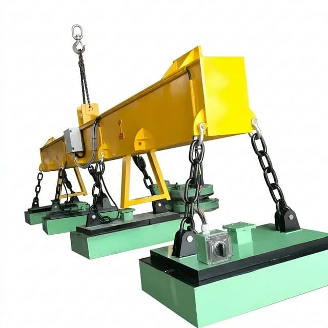
Illustrative lifting assembly from the product library; the photograph does not establish the modules' switching technology, lifting rating or test performance.
Magnetic workholding can give a cutter access to five faces of a ferromagnetic part without repositioning mechanical clamps. The right choice depends on the complete process: material, contact geometry, holding time, cutting or acceleration loads, and release behavior.
[Factory Workholding Choice]
  ├─ Electromagnet: continuous holding current; assess supply-loss protection.
  └─ EPM: pulsed switching; retained magnetic state; validate holding and release.
Evaluate three costs together: power-loss protection, heat introduced by the holding coil, and installed lifecycle cost. EPM avoids continuous holding-coil current, while an electromagnet can offer useful force adjustment. Neither principle alone determines usable force, safe working load or machining accuracy.
2. The Physics: Dual-Magnet Flux Steering vs. Continuous Ampere-Turns
The Conventional Electromagnet: Dynamic Ampere-Turns
A conventional electromagnet uses an energized coil and a ferromagnetic core. For a simplified uniform magnetic path:
B ≈ μ × N × I / lHere N is turns, I current, μ permeability and l path length. This approximation omits air-gap reluctance, leakage and steel saturation; it is not a force-sizing equation for an industrial chuck. Continuous coil heating follows:
P_coil = I² × R_coilAfter supply removal, field decay depends on the driver and suppression circuit; remanence can remain. Do not assume either an instantaneous release or adequate residual holding force.
The Electro-Permanent Magnet (EPM): Dual-Magnet Flux Steering
EPM switches permanent magnetic flux with electrical excitation. SPD's technology explanation confirms that electrical energy is needed during magnetization and demagnetization rather than throughout holding.
A common architecture combines a high-coercivity fixed magnet, such as NdFeB, with a reversible magnet, such as AlNiCo, and soft-iron return paths. Material grades, switching voltage, peak current and cycle duration depend on the product. Do not size a controller from a generic millisecond or ampere range.
The Magnetization (MAG) State — Clamped
A controlled pulse sets the reversible magnet so flux crosses the pole faces and ferromagnetic workpiece. The magnet then retains this state without continuous holding-coil current. Sensors, PLCs and the controller can still draw power.
The Demagnetization (DEMAG) State — Released
A reverse pulse changes the reversible magnet's state so more flux returns inside the housing. Switching OFF is distinct from demagnetizing the workpiece: leakage and part remanence may remain. Release capability must be checked with the actual controller and part.
3. Visual Architecture: Internal Flux Paths in Clamped vs. Released States (SVG)
The following schematic illustrates the internal flux steering mechanism that enables an EPM to redirect flux between a holding state and a release state without mechanically moving the magnets. This is a conceptual schematic, not a dimensioned design or a measured field map:
Figure 1: Electro-Permanent Magnet (EPM) Internal Flux Switching Principles
Conceptual MAG and DEMAG flux paths; no continuous holding-coil power. Controller standby is separate.
4. Safety & Blackout Integrity: EN 13155 and Battery Backup Realities
EPM retains its magnetic state when supply power fails. Contact loss, overload, peeling, overheating or an unintended release command can still defeat retention. Never plan a route over people or leave a suspended load unattended.
The European Standard EN 13155 Framework
EN 13155 concerns non-fixed lifting attachments; stationary machining fixtures require a different machine and process risk assessment. It is not a worldwide blanket approval. Have the supplier identify the applicable edition, magnet category, working load limit (WLL), breakaway test conditions and required safeguards. Do not derive a WLL from a generic 2:1 or 3:1 comparison in a purchasing article.
HSE's magnetic lifting guidance discusses supply-loss warnings, standby power and protection against unintended release. Its external-supply example above 20 kg SWL calls for at least ten minutes of backup holding. The page references an older EN 13155 edition; use it for hazard guidance, not confirmation of today's applicable standard edition or an unrestricted backup exemption.
Battery Backup and Maintenance in the RFQ
For each proposed architecture, request a documented supply-loss test, alarm behavior and recovery procedure. Include a severed downstream cable in the fault assessment: a charged upstream battery alone does not address that failure.
Ask for the manufacturer's inspection, battery capacity-test and replacement schedules. This guide does not establish a universal monthly test requirement or two-year battery replacement rule. EPM still needs inspection and controller, cable and pole-face maintenance.
5. Thermal Drift & Machining Accuracy: The Hidden Cost of Joule Heating
An EPM chuck avoids continuous holding-coil heating, removing one source of thermal drift. It does not remove heat from cutting, coolant, the machine or repeated switching.
The Thermal Expansion Formula in Magnetic Clamping
For a freely expanding, uniformly heated steel length:
ΔL = α × L₀ × ΔTUse α = 11.5 × 10⁻⁶ / K as an illustrative steel coefficient; obtain the actual value for the material and temperature range.
Illustrative Thermal Drift Calculation — Not a Test Result
For L₀ = 800 mm, an assumed uniform rise of 40 K gives ΔL = 0.368 mm (368 micrometres). An assumed rise of 1 K gives 0.0092 mm (9.2 micrometres). Neither temperature is a measured or guaranteed value for either technology.
Length expansion is not face bowing, flatness error or parallelism. Those require temperature-gradient measurements and a mechanical model or fixture test. Verify cold-to-stabilized part dimensions over the actual machining cycle before accepting a precision claim.
6. Demagnetization & Clean Release: Eliminating the Residual Magnetism Dilemma
Part sticking can arise from both decaying coil current and magnetic remanence in the magnet or workpiece. Driver suppression affects current decay; steel grade and heat treatment affect remanence. See the related residual magnetism and release latency guide.
Switching OFF Is Not a Residual-Field Guarantee
EPM controllers differ. A reverse switching pulse may be followed by a demagnetization sequence, but the number of pulses and achieved residual field are product- and workpiece-specific. Conventional electromagnetic chuck controllers may also offer demagnetization.
For automated handling, specify a maximum release delay and an agreed residual-field measurement method: probe type, distance, location and workpiece condition. Measure actual part detachment as well as field strength; a low reading at one location does not establish reliable release. Do not assume a universal less-than-5-gauss result or a zero-sticking guarantee.
7. Financial TCO & Energy Audit: 5-Year Lifecycle Cost Modeling
Hypothetical budgeting example, not supplier quotations or operating records. Compare one lifting-beam installation at 8 holding hours/day, 250 days/year and USD $0.18/kWh. No lifting capacity is established by this example. All purchase and service costs below are assumed inputs.
Energy assumptions: the electromagnet draws 4.2 kW from the supply while holding. EPM switching uses an assumed supply-side average of 1.5 kW for 0.6 seconds per pulse, 120 individual pulses/day including both clamp and release pulses, plus 5 W of controller standby during the 2,000 operating hours/year. Power is isolated outside those hours. Actual systems may have different idle consumption or charging losses; meter supply energy rather than using peak coil power.
Table 1: Illustrative 5-Year Lifecycle Cost Breakdown
| Cost Component | Conventional Electromagnet with Backup | EPM System | Procurement Interpretation |
|---|---|---|---|
| Initial installed cost | $14,500 | $22,800 | Assumed $8,300 EPM premium; obtain like-for-like quotations. |
| Annual energy | 8,400 kWh; $1,512 | 17.5 kWh; $3.15 | Includes the stated EPM pulse and standby assumptions. |
| 5-year energy cost | $7,560 | $15.75 | Fixed tariff; no escalation or discounting. |
| Battery replacements over 5 years | $3,600 | $0 | Assumes two $1,800 replacements; no battery fitted to this hypothetical EPM design. |
| Battery-specific testing labor over 5 years | $3,000 | $0 | Assumed $50/month; EPM inspection is still required. |
| Cable replacement over 5 years | $1,800 | $800 | Assumed allowances, not a universal cable-life advantage. |
| Additional cabinet cooling over 5 years | $1,200 | $0 | Site-specific assumption; omit if neither proposal needs cooling. |
| Total modeled 5-year TCO | $31,660 | $23,615.75 | Modeled EPM saving: $8,044.25. |
Reproduce the calculation:
Electromagnet annual energy = 4.2 × 8 × 250 = 8,400 kWh
EPM pulse energy/year = 1.5 × (0.6 / 3,600) × 120 × 250 = 7.5 kWh
EPM standby energy/year = 0.005 × 8 × 250 = 10 kWh
EPM annual energy cost = (7.5 + 10) × $0.18 = $3.15
5-year operating-cost difference = $17,160 − $815.75 = $16,344.25
Simple payback = $8,300 / ($16,344.25 / 5) = 2.54 years ≈ 30.5 months
Energy-only payback = $8,300 / ($1,512 − $3.15) ≈ 5.5 years
The 30.5-month result spreads modeled service costs evenly; actual cash break-even depends on when replacements occur. Common inspections, taxes, financing, downtime, controller repairs and disposal are excluded from both totals. Add differing costs from the proposals. Lower utilization, lower tariffs or an efficient electromagnetic supply can substantially reduce the EPM advantage; a three-shift plant needs its own calculation.
Comparing quotations? Send the proposed power figures and operating schedule for review, including pulse count and standby hours, so the comparison uses your duty cycle.
8. Comprehensive Engineering Specification Matrix
Use this matrix to define supplier questions. Numerical limits must come from the selected model's documentation and application tests.
Table 2: Technical & Operational Comparison Matrix
| Engineering Parameter | Conventional Electromagnet | EPM | Selection Boundary |
|---|---|---|---|
| Holding principle | Energized coil produces flux. | Electrically switched permanent flux. | Compare complete magnet-and-controller assemblies. |
| Holding energy | Continuous coil current. | No continuous holding-coil current. | Include controller, monitoring and switching energy. |
| Loss of supply | Holding can be lost as current decays. | Magnetic state is retained. | Retention is not protection against every mechanical or control fault. |
| Lifting rating | Application-specific WLL and safeguards. | Application-specific WLL and safeguards. | Require applicable standard edition and breakaway test conditions. |
| Heat and accuracy | Coil heat can contribute to drift. | Removes continuous holding-coil heating. | Validate dimensional stability during the actual process. |
| Force adjustment | Current adjustment may be available. | Selectable magnetization levels may be available. | Force is not generally linear with current; obtain control curves. |
| Release and remanence | Driver decay and steel remanence matter. | Switching and workpiece remanence matter. | Specify release time and residual-field acceptance. |
| Pole pitch and thickness | Product-specific. | Product-specific. | Match the smallest part and thinnest section; avoid double-sheet pickup. |
| Air-gap tolerance | Force decreases as the gap grows. | Force decreases as the gap grows. | Use tested force-gap curves for the actual surface. |
| Temperature | Limited by the entire assembly. | Limited by the entire assembly and magnet grades. | Insulation class or Curie temperature alone is not a working-temperature rating. |
| Controls and interlocks | Supply, driver and fault detection. | Switching controller and state verification. | Define verified clamp, supported release and restart behavior. |
| Installed cost | Obtain a complete quotation. | Obtain a complete quotation. | Include tooling, protection, integration and acceptance testing. |
As a concrete product boundary, Eclipse's Supermill documentation specifies steel plates 15–300 mm thick, pole extensions and five-side access. That range applies to that product, not all EPM chucks, thin sheets or lifting attachments.
9. Workpiece Metallurgy, Air Gaps & Penetration Depth Guidelines
Holding force belongs to the complete magnetic circuit, including the part and contact interface. A catalog pull-off value on a clean test plate is not automatically usable holding force in production.
1. Workpiece Metallurgy & Carbon Content Derating
Record the exact material grade and heat treatment. Permeability and saturation behavior differ across steels and cast irons; generic percentage derating tables cannot replace supplier data. Austenitic 304/316 are generally unsuitable for magnetic holding, even when cold work produces some magnetic response. Ferritic or martensitic stainless grades still require application testing.
2. The Real-World Air Gap Trap
Paint, scale, burrs and uneven contact increase reluctance. Record the worst credible working gap from actual parts and contamination conditions, then request a force-gap curve for the proposed pole arrangement. There is no universal force percentage at 0.1, 0.5 or 1 mm and no single minimum allowance appropriate to every installation.
3. Workpiece Thickness & Magnetic Saturation
A thin part can restrict the flux path; a field penetrating multiple sheets can cause unintended pickup. Select pole pitch and magnet spacing around the thinnest section and smallest contact footprint. Verify that a proposed fine-pole or shallow-field design still delivers sufficient usable force.
For machining, separately check cutting forces, torque, shear friction and peeling moments. For lifting, check acceleration, plate flexure, overhang and load sharing across modules. A normal pull-off test alone does not cover those load cases.
10. Pre-PO Specification & RFQ Audit Checklist
Use this checklist to compare proposals and agree factory acceptance testing (FAT) before issuing a purchase order.
- Application and jurisdiction: Identify stationary machining, robotic transfer or overhead lifting; record the applicable equipment category, standard edition and responsible integrator.
- Part definition: Supply mass, dimensions, minimum thickness, material grade, heat treatment, temperature and drawings of contact areas.
- Contact and loading: Document coating, scale, roughness, worst working gap, overhang, acceleration, cutting loads, shear and peeling moments.
- Rated performance: Obtain model-specific force-gap and thickness curves, WLL where relevant, and the test conditions behind each rating.
- Supply and controller: Specify voltage, operating hours, pulse count, standby power, switching time and verified-clamp feedback before motion.
- Fault behavior: Agree supply-loss, cable-fault, restart and inadvertent-release safeguards; define how a retained load is safely recovered.
- Temperature and sealing: Obtain full assembly ratings for workpiece heat, coolant, chemicals and washdown conditions. An IP number alone does not establish coolant or corrosion compatibility; see the potting and sealing guide.
- Tooling: Verify pole extensions, mounting, stops and minimum contact coverage against the smallest and largest parts.
- Acceptance tests: Agree witnessed holding, shear/peel, release and thermal checks appropriate to the application, using representative parts and worst agreed gaps.
- Records and service: Require traceable results, operating instructions, inspection schedules and controller/battery service allowances. Define residual-field limits and the measurement method where needed.
11. Frequently Asked Questions (FAQ)
Q1: What is the primary operational difference between an electro-permanent magnet (EPM) and a standard electromagnet?
An electromagnet needs continuous coil current to hold. An EPM uses an electrical pulse to switch permanent magnetic flux and needs no continuous holding-coil current. Its controller and monitoring equipment may still consume standby power. Neither technology establishes a safe working load without application-specific validation.
Q2: Why do precision CNC milling and surface grinding operations prefer electro-permanent magnetic chucks over electromagnets?
EPM removes continuous holding-coil heating, reducing one source of thermal drift. Cutting, coolant, ambient temperature and repeated switching still affect accuracy. Verify the complete fixture on the intended workpiece; EPM alone does not guarantee sub-micron flatness or parallelism.
Q3: How does European Standard EN 13155 treat electro-permanent lifting magnets versus conventional electric lifting magnets?
EN 13155 addresses non-fixed lifting attachments; it is not a global rule for every magnetic chuck. Ask the supplier to identify the applicable edition, magnet category, breakaway test conditions, working load limit and power-loss safeguards. This guide does not certify a universal safety factor or backup exemption.
Q4: How does an electro-permanent magnet release a workpiece without residual magnetic sticking?
A reverse switching pulse redirects much of the flux into the magnet housing. Some controllers also provide a demagnetization sequence. Residual attraction depends on the controller, pole geometry and workpiece material, so verify release time and residual field on actual parts rather than assuming zero remanence.
Q5: What are the key trade-offs between CapEx and OpEx for EPM systems?
Compare actual installed quotations with metered holding energy, switching energy, controller standby power and maintenance. In this guide's hypothetical scenario, the EPM premium is $8,300 and modeled five-year savings are $8,044.25. Simple payback is about 30.5 months under all listed assumptions, not a guaranteed supplier result.
Q6: When is a conventional electromagnet still the preferred choice over an EPM?
Consider an electromagnet where controllable force, a validated scrap-handling pole geometry or low utilization favors its installed cost. Force is not generally linear with current. For hot work, specify a complete temperature-rated assembly; winding insulation class and permanent-magnet Curie temperature are not assembly operating limits.
12. Authoritative Sources & Standards
Sources checked on 2026-10-28. Regulator guidance identifies hazards; manufacturer pages describe their own technology or products. None supplies test evidence for ElectromagnetMaker equipment or validates the hypothetical cost inputs above.
- HSE — Magnetic lifting devices: UK regulator guidance on power-loss protection, release controls and operating precautions. It references an older EN 13155 edition; confirm the applicable edition separately for the purchase.
- SPD — Electro-permanent technology: manufacturer explanation of electrically switched permanent flux and energy use during magnetization/demagnetization. It does not establish universal pulse times or residual-field limits.
- Eclipse Magnetics — Supermill magnetic chuck: a specific milling chuck example with power-loss retention, pole extensions, five-side access and a stated 15–300 mm plate range. Product claims are not independent comparative testing.
Need Engineering Support for Magnetic Workholding or Lifting?
Request an application review with the checklist above, your drawing, material grade, minimum thickness, working gap and duty cycle. Ask for the proposed model's ratings, acceptance-test scope and installed quotation before comparing cost or approving equipment.
Related selection resources: holding electromagnets, lifting electromagnets and custom electromagnet sourcing.
Autor

Categorías
Más artículos
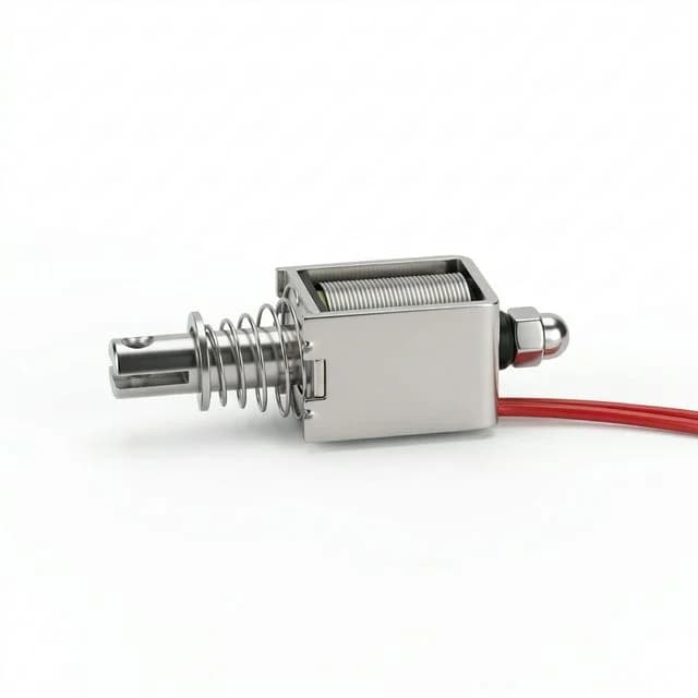
Bistable Latching Solenoids: Zero-Power Holding Guide for AGV/AMR Design
Specify bistable latching solenoids for 2026 battery-powered robotics. Compare monostable vs latching, driver circuits, thermal management, and TCO for AMRs.
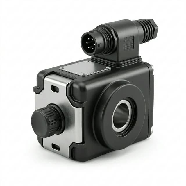
Electromagnet & Solenoid Market Update (2026-W17): Discontinuation Risk and Buyer Controls
Decision update for OEM buyers: April 2026 solenoid discontinuation signal, where replacement gaps are real, and how to update RFQs for cost, lead-time, and field-fit control.
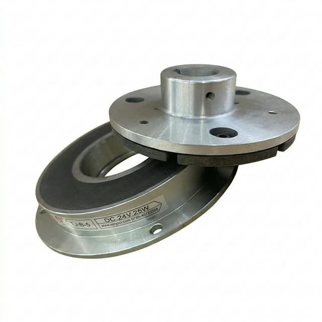
Power-Off vs. Power-On Electromagnetic Brakes: The 2026 Engineering Guide to Dynamic Stopping, Response Latency, and Thermal Sizing
Compare power-off vs power-on electromagnetic brakes for dynamic torque, stopping distance, coil heat, and RFQ checks. Request an engineering application review.
