
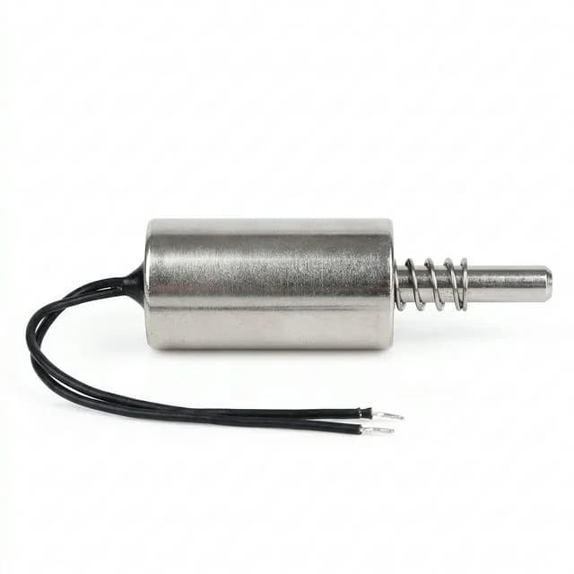
Residual Magnetism & Solenoid Release Latency: The 2026 Engineering Guide to Eliminating Sticking Parts and Plungers
Troubleshoot residual magnetism and solenoid release delays. Compare clamps, core materials, shims and springs, then define RFQ tests. Request engineering help.
One-Line Decision: For residual magnetism and solenoid release delays, first measure coil current and armature motion together. If current persists, review the suppression circuit; if sticking remains at zero current, investigate residual attraction, contact gap, oil films and return force before changing the design.
Need help diagnosing release delays? Contact our application engineering team with your driver and load details, or review our holding electromagnets, spring-return solenoids, custom electromagnets, and continuous-duty solenoids.
Published / reviewed: 2026-10-26. Scope: Global engineering and procurement guidance for conventional DC electromagnets and spring-return solenoids. Magnetic chucks are discussed only for demagnetization context. Permanent-magnet latching devices need their own release sequence; this guide is not an acceptance standard for lifting or safety functions.
Evidence and limitations: This is a source-based design guide, not an ElectromagnetMaker laboratory test report. The calculations are illustrative screening models; release time, gap thickness, spring margin and material suitability require tests on the actual driver, core and workpiece. No universal millisecond target or material grade guarantees release.
Quick Navigation
- 1. Executive Summary: The "Ghost Force" Dilemma
- 2. The Physics: Remanence, Coercivity, and the B-H Loop
- 3. The Triad of Release Latency
- 4. Electrical Decay: How Flyback Diodes Affect Release Time
- 5. Magnetic Core Metallurgy & Qualified Annealing (Selection Table)
- 6. Mechanical Solutions: Anti-Residual Shims & Ejector Pins
- 7. Visualizing Release Dynamics: Diode vs. Zener vs. Reverse Pulse (SVG)
- 8. Active Demagnetization Circuits for Heavy Workholding
- 9. Sizing the Return Spring: Sizing Formulas & Preload Margins
- 10. Troubleshooting Matrix: Diagnostic Guide for Sticking Plungers
- 11. The Procurement Audit: RFQ & Factory Acceptance Checklist
- 12. FAQ for Procurement & Automation Engineers
- 13. Sources and References
1. Executive Summary: The "Ghost Force" Dilemma
Few issues cause more frustration on automated assembly lines, high-speed sorting conveyors, and robotic end-of-arm tooling (EOAT) than an electromagnet or solenoid that refuses to let go.
Consider a holding magnet whose lightweight workpiece stays attached after switch-off, or a diverter solenoid whose return motion misses the controller deadline. These are diagnostic scenarios, not measured customer cases.
On the factory floor, technicians often misdiagnose this as mechanical binding, dirty guides, or weak return springs. A heavier spring can then consume the available pull-in margin, causing intermittent actuation or extending the commanded on-time beyond the intended duty cycle.
Delayed release and armature sticking can involve three interrelated domains:
- Electrical decay latency: Coil current continues to circulate through a suppression path after switch-off.
- Magnetic material remanence: Attraction from magnetization retained in the core or workpiece after current falls; processing and magnetic history influence it.
- Mechanical boundary effects: Friction, binding, oil-film adhesion and the contact condition.
For procurement teams, a nominal holding-force rating is therefore insufficient. Request a defined release endpoint, the intended driver topology, and test records at the relevant temperatures, orientations and workpiece conditions.
2. The Physics: Remanence, Coercivity, and the B-H Loop
To solve release latency, engineering teams must evaluate the magnetic hysteresis loop (B-H curve) of the ferromagnetic circuit.
Reading a B-H loop: remanence describes the induction remaining at zero applied field after a stated magnetic history; coercivity describes the reverse field needed to bring that induction to zero. These material measurements are not finished-assembly release-force ratings.
Coil current produces magnetizing field H; whether the core saturates depends on the current and magnetic circuit. Ferromagnetic material can remain magnetized at zero current. In an assembly with air gaps and a workpiece, the operating point also depends on the circuit geometry and demagnetizing field; it is not necessarily the material-loop remanence Br.
For an approximately uniform field normal to an effective pole area, the Maxwell-stress estimate is:
F ≈ B_gap² × A_effective / (2 × μ0)
μ0 ≈ 4π × 10⁻⁷ H/m
Here F is force in newtons, B_gap is flux density in the working gap in tesla, and A_effective is area in square metres. Fringing, leakage, saturation and non-uniform contact limit this approximation. Do not substitute a material datasheet's Br for measured gap flux.
The Zero-Gap Trap
Illustrative calculation: if the same effective area has 1.50 T energized gap flux and 0.35 T residual gap flux, the force ratio is (0.35 / 1.50)² ≈ 5.4%. Applied to an assumed 2,000 N energized force, that is about 109 N of residual attraction, versus about 4.9 N of weight for a 0.5 kg part. The flux values are assumptions, not properties assigned to 1018, DT4 or any supplied product.
A low-coercivity material can help a circuit demagnetize, but does not establish zero remanence or zero sticking. A reverse field sufficient to cancel a material test loop also does not specify the pulse needed by a complete magnet and workpiece.
3. The Triad of Release Latency
When a PLC commands OFF, current decay, magnetic diffusion and motion can overlap. Treat them as diagnostic contributions, rather than three independent delays that must be added.
Stage 1: Electrical Current Decay
The clamp topology, initial current, winding resistance and position-dependent inductance govern how current falls. Observe current through the coil, not just the PLC command voltage.
Stage 2: Magnetic Field Decay
Residual magnetization and eddy currents in conducting cores can keep attraction present as the coil current falls. The contribution depends on material and geometry; it cannot be assigned a universal millisecond allowance.
Stage 3: Mechanical Separation & Transit
Motion begins when available separating force exceeds magnetic attraction and other resisting loads. Friction, load, stroke and spring force then affect transit time.
Kendrion's time definitions distinguish release delay t21 (switch-off to start of return) from return time t22 (motion to the initial position), with total release time t2 = t21 + t22. For workpiece handling, also specify when the part has physically cleared the magnet.
4. Electrical Decay: How Flyback Diodes Affect Release Time
A standard flyback diode is a valid low-voltage suppression choice, but can be unsuitable when the release deadline requires faster current decay. Check the actual coil current and driver limits before selecting a replacement.
The Physics of the Diode Clamp Trap
When the driving switch (MOSFET or relay) opens, the coil forces current to continue flowing in the same direction. With a standard flyback diode, that current circulates in a closed loop through the coil winding resistance (R_coil) and the forward diode drop (V_D, which varies with current and temperature).
The differential equation governing this discharge loop is:
-L × di/dt = i(t) × R_coil + V_DFor approximately constant inductance, the stored energy is E = 0.5 × L × I². Winding resistance and diode forward voltage dissipate this energy. The L/R scale is useful when the resistive voltage dominates:
tau ≈ L / R_coilThe armature starts returning when net separating force exceeds attraction. The corresponding drop-out current depends on position, load, spring and magnetic history; it is not a fixed fraction of pull-in current.
The Solution: Fast-Decay Clamping Topologies
To accelerate current decay, the circuit must force the back-EMF voltage to climb to a controlled high level. According to Faraday's Law (di/dt = -V / L), higher clamp voltage produces a steeper rate of current decay:
di/dt = -(V_clamp + V_D + i × R_coil) / LA correctly oriented series diode and Zener path, or a suitably selected bidirectional TVS across the coil, permits a higher opposing voltage. Actual clamp voltage varies with pulse current and temperature. A bare unidirectional TVS placed like a flyback diode can simply conduct forward and fail to give the intended fast decay.
For a low-side switch with a clamp across the coil, check V_DS_peak ≈ V_supply_max + V_clamp_at_current + wiring_overshoot. Include tolerances, pulse energy, repetition rate, temperature derating and coil insulation. An internal driver clamp may use a different voltage reference. See TI SLVAE59A, section 3.2 for current paths and clamp design.
Reproducible calculation, not a release-time test: assume L = 0.10 H, R = 24 Ω, initial current I0 = 1 A and a fixed, motionless core. For a constant opposing clamp drop Vc, integrating the loop equation gives:
t(I0 → I1) = (L / R) × ln[(R × I0 + Vc) / (R × I1 + Vc)]
Stored energy at I0 = 0.5 × L × I0² = 0.05 J
At an illustrative threshold I1 = 0.20 A, Vc = 0.7 V gives about 6.25 ms, while Vc = 36.7 V gives about 1.59 ms. These are electrical decay estimates only; the threshold and inductance must be established for the actual actuator. Neither value predicts complete mechanical release.
Coil De-energization Circuit Comparison Matrix
The six options below compare design trade-offs, not universal release times or component prices.
| Circuit topology | Current decay mechanism | Low-side switch voltage consideration | Energy destination | Main selection check | Suitable starting point |
|---|---|---|---|---|---|
| Freewheeling diode | Low opposing voltage; relatively slow decay | Supply plus diode drop and overshoot | Winding and diode | Pulse current and measured release deadline | Applications that tolerate a longer return delay |
| Diode + resistor | Additional resistive drop speeds decay | Supply plus current-dependent resistor/diode drop | Resistor, winding and diode | Resistor pulse energy and peak voltage | Adjustable passive suppression |
| Diode + Zener | Higher controlled opposing voltage | Supply plus actual Zener clamp and diode drop | Zener, winding and diode | Clamp tolerance, repetitive energy and temperature | Faster release with a compatible switch |
| Bidirectional TVS | Avalanche clamp across the coil | Supply plus actual TVS clamp voltage | TVS and winding | Stand-off above supply; clamp below circuit limits | Compact transient suppression |
| MOV / varistor | Nonlinear voltage-dependent clamp | Supply plus specified clamping voltage | Varistor and winding | Pulse life, tolerance and energy derating | Designs validated for the chosen pulse duty |
| H-bridge fast decay / controlled reversal | Applies opposing voltage through a defined bridge state | Depends on bridge and recirculation path | Can return energy to bus | Bus absorption, dead time and current limit | Controlled decay or calibrated demagnetization |
Driver review: Send the coil rating, driver schematic and required release endpoint to discuss a compatible actuator and suppression circuit.
5. Magnetic Core Metallurgy & Qualified Annealing
Core material and its processing condition affect hysteresis; they do not independently determine release force.
The Impact of Composition and Cold Work
Carbon and processing history matter. The ARMCO Pure Iron bulletin, printed pages 9–14 documents how mechanical stress changes magnetic properties and how annealing can restore them. It also lists ranges rather than a single guaranteed coercivity for every part.
Specify a Qualified Annealing Process
Do not prescribe one furnace recipe for every soft-magnetic grade. Ask the supplier to document the alloy, finished-part condition, atmosphere, thermal cycle, dimensional effects and magnetic acceptance method. A hydrogen process and a vacuum process are distinct; neither name alone certifies finished-assembly release performance.
Ferromagnetic Core Material Selection Matrix
This is a procurement screening framework, not a numerical ranking of coercivity, remanence or cost. Grade-specific properties require a current supplier datasheet and stated test conditions.
| Material candidate | Why consider it | Release-related limitation | Evidence to request |
|---|---|---|---|
| Low-carbon steel, e.g. 1010 / 1018 | Candidate where structural and magnetic requirements overlap | Grade alone does not specify magnetic condition or release | Finished-condition B-H data and assembly release test |
| Free-machining steel, e.g. 12L14 / 1215 | Candidate where machining efficiency is important | Do not substitute for qualified core stock without approval | Composition, magnetic data and change-control agreement |
| DT4-family electromagnetic iron | Candidate for a soft-magnetic core or plunger | Grade suffixes and delivery conditions require confirmation | Applicable grade specification and post-processing test |
| ARMCO Pure Iron | Supplier publishes processing-dependent magnetic data | Not an automatic equivalent to every DT4 grade | Exact grade, anneal condition and matching test method |
| Electrical steel / laminated construction | Candidate when eddy-current behavior matters | Lamination geometry changes assembly design | Stack design and measured dynamic response |
| Nickel-iron soft-magnetic alloy | Candidate for specialist magnetic requirements | High permeability does not guarantee release or adequate force | Saturation behavior, processing data and assembly test |
6. Mechanical Solutions: Anti-Residual Shims & Ejector Pins
Low-coercivity iron can still attract a workpiece after turn-off. A defined contact gap or a mechanical ejector provides an additional design lever, subject to energized force and wear validation.
Pole face | non-magnetic spacer | armature / workpiece
          <--- specified gap --->
The spacer thickness is a drawing-controlled dimension; actual contact flatness and wear also affect the magnetic circuit.
1. Calibrated Non-Magnetic Air-Gap Shims
Magnetic flux drops precipitously across even microscopic non-magnetic gaps. By placing a thin sheet of non-ferromagnetic material permanently on the pole face, a physical air gap is maintained even when the armature is in full contact.
Brass and other verified non-magnetic spacers are candidates. Stainless steel and coatings must be checked in their delivered and processed condition; forming, wear or heat treatment can change their behavior.
A 0.10 mm spacer is an illustrative trial thickness, not a diameter-based sizing rule. Sweep practical thicknesses on prototype assemblies and record residual pull-off force, energized holding force and release time. There is no universal inverse-square gap law for an entire magnetic circuit and no fixed percentage improvement from a 0.10 mm gap.
Design trade-off: a larger effective gap can reduce both residual attraction and useful energized force. Select it from the measured force budget and verify retention after wear.
2. Spring-Loaded Center Ejector Pins
A spring-loaded center pin can separate a workpiece when current falls sufficiently. Geeplus documents ejector pins for residual-magnetism release; their force cost and geometry are product-specific.
- Energized state: the magnet must overcome the pin force as well as the application load.
- De-energized state: the pin must overcome the worst residual attraction, friction and surface adhesion across its useful travel.
- Acceptance check: verify clean separation and adequate energized holding force with the actual workpiece, orientation and worn contact condition.
3. Surface Texture and Oil Relief
Smooth faces with lubricant or condensation can stick through viscous film resistance and capillary effects, even with low magnetic attraction. Compare controlled dry and lubricated tests while keeping geometry, current and orientation unchanged.
Relief grooves, surface texture or ejectors may help, but dimensions require an application drawing and force test. A paper spacer changes both the liquid film and magnetic gap, so its effect alone does not prove which mechanism caused sticking.
7. Visualizing Release Dynamics: Diode vs. Zener vs. Reverse Pulse
The following diagram is conceptual, not measured and not to scale. Solid curves show current; dashed curves suggest return motion. It illustrates possible behavior rather than a universal ranking: the reverse pulse and mechanical response must be tuned independently.
- Red: low-voltage freewheeling can prolong current decay.
- Blue: a higher-voltage clamp can shorten current decay.
- Green: controlled reversal can cross zero current; excessive reversal can create attraction again.
Conceptual current decay and armature return — not to scale
Solid: current. Dashed: possible return motion. ElectromagnetMaker editorial schematic; not a laboratory benchmark. Threshold, time spacing and motion are illustrative.
8. Active Demagnetization Circuits for Heavy Workholding
Workpiece magnetization can matter as much as the core. Where a controlled contact gap or ejector is insufficient, a suitable bidirectional driver can be evaluated for demagnetization.
Reverse-Pulse Demagnetization (De-gaussing)
- Decay the main current: use a defined, protected current path and monitor the actual current.
- Calibrate a reverse pulse: establish current amplitude and duration experimentally for the core and representative workpieces. There is no generally valid percentage of nominal voltage or current.
- Evaluate decreasing alternating current if needed: a controlled sequence can reduce remaining magnetization in some applications. Specify waveform, endpoint and residual-field measurement position.
Reversing current does not make an ordinary iron plunger repel: attraction depends on field magnitude and geometry. Too much reverse current can remagnetize the circuit in the opposite direction. Confirm both part separation and downstream residual field; do not infer either from a zero-current crossing alone.
9. Sizing the Return Spring: Sizing Formulas & Preload Margins
When designing spring-return linear solenoids or holding electromagnets, a frequent engineering mistake is calculating the return spring force based solely on the dynamic stroke work, while overlooking the installed preload force at zero stroke (s = 0).
The Seated Release Condition
Use measured finished-assembly residual pull-off force rather than a material-loop Br calculation:
F_preload,seated > F_residual,max + F_friction,max + F_gravity,opposingAdd a documented allowance for tolerance, wear, contamination and the required return acceleration. The inequality is a static screening condition; it does not establish release time. A fixed 2.5× multiplier is not a universal standard.
Illustrative force budget: if residual attraction is 2 N, friction is 1 N and opposing gravity is 1 N, the static demand is 4 N. A design team might provisionally allocate 6 N seated preload, leaving 2 N for uncertainty and acceleration. That allocation still needs hot/cold release and life testing.
Check Pull-In over the Entire Stroke
At each position, the hot-coil magnetic force at minimum supply voltage must exceed spring force plus the opposing application load. Use the actual linkage and spring compression: for many pull-in solenoids, spring compression increases as the plunger seats, while magnetic pull-in force is weakest at the largest gap.
A low-rate spring may help, but compare the full force-versus-stroke curves before approval. Verify the final assembly's release-time distribution rather than accepting preload alone.
10. Troubleshooting Matrix: Diagnostic Guide for Sticking Plungers
When troubleshooting sticking actuators in the field or qualifying prototype samples, use this structured engineering matrix to identify root causes and deploy permanent corrective actions:
Field Troubleshooting & Failure Mode Analysis
| Observed symptom | Diagnostic test | Possible cause | Corrective action to evaluate |
|---|---|---|---|
| Releases on bench but slowly from PLC output | Record command, coil current and motion with each driver | Different built-in suppression or current regulation | Confirm output limits and validate a compatible clamp; do not remove protection without a rated replacement |
| Dry parts release; oily parts stick | Compare controlled dry/oily tests at the same current and gap | Film adhesion combined with magnetic attraction | Evaluate cleaning, relief features or an ejector and retest holding force |
| Release worsens after cycling | Inspect gap, wear, debris and spring force | Spacer wear, contamination or fatigue | Restore the drawing-controlled gap or spring condition and repeat the life test |
| A new batch has higher residual attraction | Compare material certificates, processing records and finished-part tests | Material or process variation, geometry or coating changes | Investigate the difference before assigning a cause; require approved change control |
| Sticks at high ambient temperature | Measure clearances, current and friction at temperature | Thermal binding, lubrication change or driver behavior | Resolve the measured constraint and verify both hot pull-in and release |
| Parts separate but retain magnetism downstream | Measure workpiece field at a defined location after release | Workpiece remanence | Evaluate a calibrated demagnetization sequence or separate degaussing station |
11. The Procurement Audit: RFQ & Factory Acceptance Checklist
Procurement teams must ensure that release time and residual magnetism requirements are explicitly stated in the RFQ and verified during Factory Acceptance Testing (FAT).
Use the following checklist to audit vendor quotes and prevent field warranty claims:
Pre-PO Sourcing & Specification Checklist
- Material and condition: identify the core and plunger grade, governing specification and finished-part processing condition; approve any proposed equivalent explicitly.
- Magnetic evidence: request grade-specific B-H/coercivity data with a stated test method and heat-treatment record; do not treat low coercivity as a release guarantee.
- Gap and surfaces: specify spacer/coating material, thickness, tolerance, contact flatness and the wear condition used for acceptance.
- Release endpoint and deadline: define command reference and motion endpoint. For example, an application may require return to a stated sensor position within 12 ms; this is a negotiated requirement, not a generic product capability.
- Force budget: document seated residual force, friction, opposing gravity and spring allowance, then verify pull-in over the full stroke at hot-coil/minimum-voltage conditions.
- Driver alignment: record the actual supply range, turn-off current, suppression topology, clamp waveform and switch limits. Test the production driver rather than an unrelated laboratory supply.
- Repeatable FAT / incoming QC: agree sample size and cycles from the application risk. Capture command, coil current and position together; record instrument bandwidth, coil/ambient temperature, orientation, load, gap and clean/oily surface condition. Report maximum observed release time and any non-release events, not just an average.
- Residual-field test where required: define probe type, orientation, distance, location and elapsed time after switch-off, plus an application-specific limit. A Gauss reading alone is not a residual holding-force measurement.
Keep the oscilloscope traces and sample identifiers with the acceptance record. Repeat the agreed corner conditions after the specified wear test; a handful of room-temperature cycles does not establish lifetime reliability.
Preparing an RFQ? Send your stroke, load, cycle rate, driver schematic and required release endpoint so the application team can discuss a suitable solenoid or holding magnet and a verifiable acceptance plan.
12. FAQ for Procurement & Automation Engineers
Q: Why does an electromagnet or solenoid still hold onto a part after the power is switched off?
Possible causes include coil current still circulating through the suppression circuit, magnetic remanence in the core or workpiece, and mechanical friction or oil-film adhesion. Record coil current and armature motion together before choosing a remedy.
Q: How much does a standard flyback diode increase solenoid release time?
There is no universal delay. It depends on inductance, winding resistance, initial current, the driver and the mechanical load. A diode usually permits slower current decay than a higher-voltage clamp; compare both on the same actuator under the specified operating conditions.
Q: What is an anti-residual air gap shim, and how does it prevent magnetic sticking?
A non-magnetic shim maintains separation between the pole face and armature, increasing magnetic reluctance. It can reduce residual attraction but also reduces energized holding force. Select thickness by measuring both forces and release time on the actual assembly.
Q: What core material should be specified in an RFQ for low residual magnetism?
Specify a documented soft-magnetic grade, its finished-part processing condition and an agreed magnetic test method. DT4-family iron or ARMCO Pure Iron may be candidates, but grade names are not interchangeable certificates and low coercivity alone does not guarantee release.
Q: How should return springs be sized to prevent armature hang-up?
At the seated position, spring force must exceed the worst measured residual attraction, friction and opposing gravity with an agreed margin. Also verify that the hot coil at minimum supply voltage can pull in against the spring and load over the full stroke.
Q: Can reverse-polarity demagnetization pulses be used on DC electromagnets?
A suitable bidirectional driver can apply a calibrated reverse-current pulse or decreasing alternating sequence. Tune it for the core, workpiece and load; excessive reverse current can remagnetize the parts. Reversing polarity alone does not make a ferromagnetic plunger repel.
13. Sources and References
These four manufacturer sources support the principles noted below. They do not certify ElectromagnetMaker products, the illustrative calculations, or an application-specific release deadline. Reviewed 2026-10-26.
- Kendrion — Technical definitions, section 1.6 (printed page 6) and suppressor circuits (printed pages 7–8): release delay, return time and suppression trade-offs. This is a manufacturer explanation referencing DIN VDE 0580, not the standard text. Read Kendrion technical definitions.
- Texas Instruments — Using Motor Drivers to Drive Solenoids, SLVAE59A, revised April 2022, section 3.2 (printed pages 9–12): freewheeling, passive clamps and H-bridge current paths. Read TI SLVAE59A.
- AK Steel International / Cliffs — ARMCO Pure Iron product data bulletin, printed pages 9–14: processing-dependent magnetic properties, stress effects and annealing. Applies to the stated material and conditions, not an equivalence claim for DT4. Read ARMCO Pure Iron bulletin.
- Geeplus — Electromagnets: manufacturer guidance on contact separation, energized holding force and spring-loaded ejector pins for residual magnetism. Read Geeplus electromagnet guidance.
Author

Categories
More Posts

Q3 2026 Sourcing Alert: How New Copper & NOES Tariffs Impact Electromagnet Costs
Q3 2026 copper and NOES tariff changes affect electromagnet, solenoid, clutch, and holding magnet RFQs. Review cost, lead-time, and spec actions.
The Shift to 48V Solenoids in AGV/AMR: 12V vs 24V vs 48V Procurement Guide
Specify 48V solenoids and electromagnets for next-gen AGV/AMR platforms. Compare 12V, 24V, and 48V architectures, thermal efficiency, wiring weight, and costs.
Electromagnet & Solenoid Market Update (2026-W16): NOES and 232
Decision update for OEM buyers: April 2026 NOES and Section 232 changes, EU GOES timeline, and the exact RFQ fields to update before the next PO cycle.