
Power-Off vs. Power-On Electromagnetic Brakes: The 2026 Engineering Guide to Dynamic Stopping, Response Latency, and Thermal Sizing
Compare power-off vs power-on electromagnetic brakes for dynamic torque, stopping distance, coil heat, and RFQ checks. Request an engineering application review.
One-Line Decision Summary: Start with power-off (spring-applied) electromagnetic brakes when the load must stop or remain held after electrical power is lost. Consider power-on (electrically engaged) brakes for powered process stopping or indexing where release on power loss is acceptable. For either architecture, confirm the selected model's dynamic-stop rating: a holding brake is not automatically suitable for repeated stopping. A fail-safe operating principle alone does not establish functional safety compliance.
Need technical validation? Request an application review with your motor inertia, operating speed, required stopping time, and duty cycle. Validate your parameters with our 24VDC Electromagnetic Brake Checker, or explore electromagnetic clutches and lifting and holding electromagnets.
Published / Reviewed: 2026-11-01. Scope: Global, English-language engineering and procurement guidance for robotics OEMs, factory automation integrators, machine tool builders, and drive system engineers selecting dry-friction electromagnetic brakes. Wet brakes, magnetic-particle brakes, and eddy-current retarders need separate selection methods.
Evidence and Limits: This is a desk-based selection framework using manufacturer publications and reproducible calculations, not a hardware test report. Numerical scenarios below are assumed examples, not measured brake performance or certification evidence. Verify the selected brake, driver, installation, and worst-case load together. Standards applicability depends on machine type and jurisdiction; public catalogue pages do not establish clause-level compliance. Review again by November 2027, or sooner if the brake, driver, or applicable standards change.
Quick Navigation
- 1. Executive Summary: The Industrial Braking Dilemma
- 2. Operating Principles: Mechanical Spring Force vs. Direct Electromagnetic Clamping
- 3. Visual Architecture: Power-Off vs. Power-On Operating States (SVG)
- 4. Dynamic Stopping vs. Static Holding: The Torque Sizing Mathematics
- 5. The Response Latency Trap: Engagement Delay, Freewheeling Diodes, and Fast Switching
- 6. AGV/AMR Stopping Distance: Worked Example and Validation Limits
- 7. Thermal Dissipation & Overexcitation (Hit-and-Hold) Control
- 8. Friction Lining Wear, Air Gap Calibration, and Failure Modes
- 9. Comprehensive Technology Specification Matrix
- 10. Electrical Switching Circuit & Response Time Comparison
- 11. 10-Point Pre-PO Specification & RFQ Audit Checklist
- 12. Frequently Asked Questions (FAQ)
- 13. Authoritative Sources & Standards
1. Executive Summary: The Industrial Braking Dilemma
In motion control, robotics, and industrial automation, brake selection starts with two different tasks: stopping a moving load and holding a stationary load. The required power-loss state is a separate decision from dynamic torque, energy capacity, and stopping frequency.
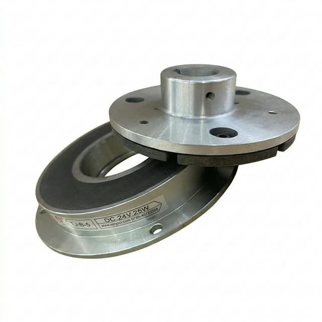
Product illustration; the photograph does not establish the model's power-loss behavior or stopping rating.
A common purchasing misconception is treating all electromagnetic brakes as interchangeable "stoppers" rated purely by nominal torque (e.g., 16 N·m). In reality:
- Power-off brakes use springs to apply friction torque. Coil power releases the brake; removing power initiates engagement after electrical and mechanical delays. An E-stop engages it only if the machine's control sequence removes brake power.
- Power-on brakes use electromagnetic attraction to clamp. Torque depends on the magnetic circuit, friction condition, and current; it is not generally linear with current. Removing power initiates release after a finite delay.
- The switching path affects stopping distance. A low-voltage flyback diode can prolong coil-current decay in a spring-applied brake. Measure engagement with the actual suppression circuit rather than reusing a catalogue time from another circuit.
Before issuing a Request for Quotation (RFQ), engineering and procurement teams must evaluate holding versus dynamic stopping requirements, thermal dissipation capabilities, driver switching topology, and air-gap wear limits.
2. Operating Principles: Mechanical Spring Force vs. Direct Electromagnetic Clamping
The mechanical and magnetic circuits of power-off and power-on electromagnetic brakes operate through opposite force pathways. The Lenze spring-applied brake flyer, page 2, illustrates the spring-clamping and electromagnetic-release mechanism; the Kendrion industrial brake overview distinguishes brake technology families and application areas.
+-----------------------------------------------------------------------------------+
| POWER-OFF (SPRING-APPLIED / FAIL-SAFE) BRAKE                                      |
|                                                                                   |
| Power State: DE-ENERGIZED (0 V / 0 W)                                             |
| Coil Field: OFF  --> Springs EXPAND --> Armature Clamps Rotor --> BRAKE LOCKED    |
|                                                                                   |
| Power State: ENERGIZED (Rated DC Voltage)                                         |
| Coil Field: ON   --> Magnet OVERCOMES Springs --> Armature Retracts --> ROTOR FREE|
+-----------------------------------------------------------------------------------+
| POWER-ON (ELECTRICALLY ENGAGED) BRAKE                                             |
|                                                                                   |
| Power State: DE-ENERGIZED (0 V / 0 W)                                             |
| Coil Field: OFF  --> Return Spring Retracts Armature --> Air Gap Open --> ROTOR FREE|
|                                                                                   |
| Power State: ENERGIZED (Rated DC Voltage)                                         |
| Coil Field: ON   --> Magnetic Flux PULLS Armature Against Rotor --> BRAKE LOCKED  |
+-----------------------------------------------------------------------------------+
The Power-Off (Spring-Applied) Mechanism
The power-off brake consists of a stationary field body containing an annular copper winding and multiple helical compression springs. An axial floating armature plate sits between the field body and a friction rotor (or disc) mounted on a splined hub keyed to the rotating drive shaft.
- De-Energized State (Holding / Braking): When the coil is unpowered, the compression springs exert continuous axial thrust against the armature plate. This clamps the friction rotor tightly against an outer mounting flange or counter-friction face. Friction torque is transferred from the rotor through the splined hub directly into the motor or gearbox shaft. No electrical power is consumed.
- Energized State (Released / Traveling): Applying the specified voltage creates a magnetic force across the armature-to-field air gap. When this force exceeds the spring force, the armature moves toward the field housing. The magnetic working gap closes while clearance opens at the friction surfaces, freeing the rotor.
The Power-On (Electrically Engaged) Mechanism
In contrast, a power-on brake resembles an electromagnetic clutch. The field housing contains a copper winding but no internal clamping springs.
- De-Energized State (Free Rotation): When the coil is unpowered, a diaphragm or leaf spring retracts the armature from the friction face. Residual drag and remanence must still be checked for the selected model.
- Energized State (Active Clamping): Energizing the coil creates an intense magnetic loop that bridges the air gap, pulling the armature plate into direct mechanical contact with the friction rotor or stationary pole face. Braking torque is created by sliding friction under active electromagnetic clamping pressure.
Critical Procurement Trade-Off
If main supply power fails:
- A power-off brake starts engaging after current and magnetic flux decay. Load movement during this delay and the available hot torque still need validation.
- A power-on brake normally releases. A vertical load therefore needs an independently validated holding provision if its release would create a hazard.
3. Visual Architecture: Power-Off vs. Power-On Operating States (SVG)
The following conceptual schematic compares operating states. Dimensions, clearances, and 24 V labels are illustrative; it is not a manufacturing drawing or proof of a stopping rating.
Figure 1: Internal Mechanical & Magnetic Circuit Architecture of Electromagnetic Brakes
Comparison of spring-applied fail-safe clamping vs. direct electromagnetic engagement across power states.
4. Dynamic Stopping vs. Static Holding: The Torque Sizing Mathematics
Static holding torque (M4) and dynamic stopping torque (M1) are separate ratings. Symbols vary between suppliers. Request the model's definitions, hot dynamic torque at operating speed, permitted emergency-stop count, and friction-work limits. There is no universal conversion from holding torque to dynamic torque. Some holding brakes permit only occasional emergency stops.
1. Total Kinetic Energy Dissipation Per Stop
For an ideal horizontal drive, with all inertia referred to the brake shaft:
W_stop = 0.5 × J_total × omega²
omega = 2 × pi × n / 60
J_load,reflected = m × (r / i)²
Here W_stop is joules, J_total is kg·m², n is shaft rpm, m is translating mass in kg, r is wheel or pulley radius in m, and i is motor speed divided by wheel speed. Add motor, rotor, gearbox, and load inertia consistently. For a ballscrew, use its travel per revolution to derive an equivalent radius. Do not count the same translating mass again as a separate energy term after reflecting it into J_total.
Transmission efficiency changes the energy and torque reaching the brake; it is not part of the geometric inertia transformation. A lowering load also releases gravitational energy. Include these effects, any motor torque during the stop, and how work is shared between multiple brakes before selecting a component.
2. Required Dynamic Deceleration Torque
M_req = J_total × delta_omega / t_decel + M_driving_load - M_resisting_loadTorques are in N·m and t_decel is the actual deceleration interval in seconds, excluding command and engagement delays. Gravity may drive a lowering load and resist an ascending one. Verify the sign and magnitude at the brake shaft. Validate stationary holding separately, including load direction and temperature.
3. Worked Torque and Thermal Screen
Illustrative inputs: J_total = 0.20 kg·m², omega = 100 rad/s, t_decel = 0.50 s, no external driving torque, and 60 identical stops per hour. Assume the brake absorbs all kinetic energy.
Required dynamic torque = 0.20 × 100 / 0.50 = 40 N·m
With an assumed service factor of 1.5: minimum dynamic torque = 60 N·m
Single-stop friction work = 0.5 × 0.20 × 100² = 1,000 J
Hourly friction work = 60 × 1,000 = 60,000 J/h
Average friction heating = 60,000 / 3,600 = 16.7 W
The assumed factor is a calculation input, not a requirement from ISO 3691-4 or a substitute for risk assessment. A candidate must satisfy all of these gates: hot dynamic torque, permissible single-stop energy at that speed, repeated-stop work and cooling interval, and lifetime wear allowance. Add coil heat to the installation's thermal assessment. An acceptable hourly average does not prove that a short, high-energy stop is permissible.
Prepare an RFQ from this screen: use the electromagnetic brake checker to organize inputs, then request the exact model's torque-speed, friction-work, and cooling data. The checker is a screening aid, not a stopping-system approval.
5. The Response Latency Trap: Engagement Delay, Freewheeling Diodes, and Fast Switching
Removing voltage does not immediately produce full braking torque. For this guide, t11 denotes engagement delay, t12 torque rise, t1 = t11 + t12 total engagement time, and t3 the subsequent deceleration interval. Confirm each supplier's measurement thresholds and terminology.
Command → current/flux decay (t11) → torque build-up (t12) → deceleration (t3)Some deceleration occurs during torque build-up. Treating the whole t1 interval as travel at unchanged speed is a simplified screening assumption; final validation needs the actual torque-time or vehicle stopping trace.
Why the Suppression Circuit Matters
A coil stores energy E = 0.5 × L × I². When current is interrupted, induced voltage follows V = -L × dI/dt. The driver needs a correctly rated suppression path to protect its semiconductor or relay contacts.
A plain flyback diode recirculates current at a low clamp voltage. That protects the switch but can delay loss of magnetic attraction and therefore spring engagement. The delay depends on inductance, resistance, current, temperature, and the brake's mechanical release threshold. Do not assign a universal 6× or 10× delay, and do not remove suppression to obtain a faster stop.
Faster Decay: Conditions for Selection
A MOV, diode-plus-Zener/TVS clamp, or an electronic fast-switching module can permit a higher controlled voltage during current decay. Confirm the brake manufacturer's approved circuit, maximum coil-terminal voltage, switch rating, polarity, pulse energy, repetitive duty, and insulation limits. Clamp voltage and mechanical engagement time must be validated together; no suppression topology guarantees a sub-20 ms engagement time for every brake.
6. AGV/AMR Stopping Distance: Worked Example and Validation Limits
ISO 3691-4:2023 covers safety requirements and verification for driverless industrial trucks and their systems. The calculation below is a transparent engineering screen, not a clause-level interpretation or compliance test.
For travel at constant speed during response delays, followed by constant deceleration on a level floor:
s_stop = v0 × (t_sensor + t_logic + t1) + v0² / (2 × a)Use seconds, m/s, and m/s² to obtain metres. Sensor and logic times must come from the actual safety equipment and configured processing chain. Brake latency must include the installed switching circuit and worst-case operating conditions.
Practical Comparison: Two Assumed Engagement Times
Assume a 1,200 kg AMR traveling at v0 = 2.0 m/s, with a = 1.8 m/s² and combined sensor/logic delay 0.080 s. Compare assumed engagement times of 0.120 s and 0.018 s; these are not measured values or claims for particular driver products.
Case A: s_stop = 2 × (0.080 + 0.120) + 4 / 3.6 = 1.511 m
Case B: s_stop = 2 × (0.080 + 0.018) + 4 / 3.6 = 1.307 m
Difference = 2 × (0.120 - 0.018) = 0.204 m (204 mm)
Mass does not appear directly because deceleration was assumed. Achieving it still requires sufficient hot brake torque and tire-floor traction: the ideal level-floor net braking force here is m × a = 2,160 N. Check vehicle stability and load retention as well as available torque.
The 204 mm difference applies only to these assumptions. A scanner protective field also needs the equipment manufacturer's allowances for sensing uncertainty, load overhang, approach conditions, and applicable installation rules. A warning field is not the same as a protective field. Validate loaded stopping performance over temperature, battery voltage, wear, floor friction, and permitted gradients; account for acceleration during latency where relevant. Neither result establishes an ISO-compliant field size or a fleet-throughput improvement.
7. Thermal Dissipation & Overexcitation (Hit-and-Hold) Control
A spring-applied brake consumes coil power while released, including any stationary interval when controls keep it released. A power-on brake consumes coil power while clamped. Friction heating during stops is a separate heat source.
Housing illustration; internal friction surfaces and thermal test results are not shown.
For an assumed 24 V, 40 W coil, nominal current is 40 / 24 = 1.67 A. Two such coils consume 80 W while energized at those conditions, or 1.28 kWh over 16 continuously energized hours. Actual energy depends on the release schedule, winding temperature, and driver.
Pull-In Current vs. Holding Current
The armature-to-field magnetic gap is largest before release. Once the armature is attracted, the magnetic gap becomes smaller, so some approved brake/driver combinations can use reduced current to maintain release. This is different from the clearance opened at the friction surfaces.
For a simplified, unsaturated, gap-dominated magnetic circuit, attraction scales approximately with I² / gap². Leakage, saturation, geometry, and residual gaps limit this model. It cannot establish a universal holding-current percentage or an allowable wear gap.
Keep Three Electrical Quantities Separate
- Boost voltage/current: Manufacturer-approved overexcitation can shorten release time. Use the specified pulse duration, current limit, repetition rate, and hot-coil checks. Do not apply double voltage to an arbitrary coil.
- Coil RMS current and loss: Winding heat is
P_copper = I_rms² × R. At fixed resistance, an illustrative current reduction to 50% produces 25% of the initial copper loss. This is not a predicted temperature reduction or permission to use that current. - PWM duty and supply power: PWM duty alone does not give RMS current. The driver topology, ripple, recirculation path, and switching frequency matter. At low ripple, average voltage can approximate duty times supply voltage, but measure current and validate minimum release-holding margin before estimating savings.
Copper resistance rises with temperature: approximately R_T = R_20 × [1 + 0.00393 × (T - 20)] near ordinary operating temperatures, with T in °C. With fixed DC voltage, current falls as resistance rises. Validate hot release at minimum supply voltage and maximum permitted air gap. No generic driver can promise a particular temperature rise or prevent every overheating failure.
8. Friction Lining Wear, Air Gap Calibration, and Failure Modes
In a spring-applied brake, lining wear can enlarge the armature-to-field working gap. The supplier must specify nominal gap, maximum gap, minimum rotor thickness, inspection interval, and any allowed adjustment procedure. These limits are model-specific.
If the gap becomes excessive, the coil may not reliably overcome the spring force. The brake can remain applied or drag during motion, overheating the lining and motor. Contamination, corrosion, low voltage, and hot windings can also impair operation; an air-gap check alone is insufficient.
Engineering Mitigations for RFQs
- Release and wear feedback: Specify whether a switch indicates armature position, wear, or both. Require documented thresholds and diagnostic behavior; a release switch alone does not measure braking torque or necessarily prove adequate lining thickness.
- Manual release: Define a controlled recovery procedure. Mechanically secure gravity loads and prevent vehicle movement before release; a hand lever is not a controlled lowering system by itself.
- Adjustment or replacement: Use only the selected model's instructions. Some brakes have non-adjustable gaps; neither a reset count nor a universal wear-sensor threshold should be assumed.
9. Comprehensive Technology Specification Matrix
This comparison applies to dry-friction brake families. The operating principle determines the normal unpowered state; the actual model determines performance and suitability.
| Technical parameter | Power-off (spring-applied) | Power-on (electrically engaged) | Engineering and sourcing impact |
|---|---|---|---|
| Braking torque origin | Mechanical springs clamp friction faces | Coil attraction supplies clamp force | Confirm the torque ratings and tested conditions. |
| Normal state after power loss | Applies after current decay and mechanical travel | Releases after current decay and mechanical travel | Validate the required safe state for the complete machine. |
| Common selection context | Power-loss holding; stopping if specifically rated | Powered process stopping or indexing | Neither family is automatically rated for every stopping duty. |
| Coil energy profile | Power consumed while released | Power consumed while clamped | Compare the actual energized schedule, not just motion time. |
| Dynamic stopping capacity | Model-dependent; some are holding-only | Model-dependent; cycling requires thermal capacity | Require dynamic torque, energy per stop, and wear-life evidence. |
| Engagement response | Depends on flux decay, springs, air gap, and circuit | Depends on current rise, air gap, and mechanics | Request worst-case traces with the proposed driver. |
| Release response | Coil must overcome springs at the installed gap | Return mechanism acts as field decays | Coordinate motor enable with validated release behavior. |
| Wear and air gap | Excessive gap may prevent reliable release | Wear can affect engagement and torque | Obtain each model's inspection and replacement criteria. |
| Manual release | Available on some designs | Normally releases without power | Define safe recovery and load restraint; confirm actual options. |
| Installed cost | Brake, driver, monitoring, maintenance | Brake, driver, possible separate holding provision | Compare the complete required function over its service life. |
10. Electrical Switching Circuit & Response Time Comparison
The following table is qualitative: there are no universal latency ranges or compliance outcomes for these topologies. Select from the brake and driver manufacturer's approved combinations, then measure the installed response.
| Switching topology | Current-decay consideration | What to request or verify |
|---|---|---|
| Plain flyback diode | Low clamp voltage may prolong current and delay spring engagement | Measured worst-case engagement; assess against the stopping budget. |
| AC-side rectifier switching | Rectifier and recirculation paths determine decay | Exact rectifier schematic, switching condition, and tested response. |
| DC-side switching with RC snubber | Response depends on resistor, capacitor, coil, and switch | Coil-terminal waveform, contact protection, and thermal duty. |
| DC-side switching with MOV | Higher clamp voltage can accelerate current decay | Rated clamp voltage, pulse energy, repetitive duty, and aging allowance. |
| Diode plus Zener/TVS clamp | Controlled higher voltage can accelerate current decay | Polarity, tolerance, peak voltage at the switch, and suppression energy. |
| Electronic fast-switching rectifier/driver | Internal switching may coordinate boost, hold, and decay | Approved brake pairing, fault behavior, timing, and hot-condition tests. |
11. 10-Point Pre-PO Specification & RFQ Audit Checklist
Before releasing a production purchase order, ask the supplier for evidence against these requirements:
- 1. Operating architecture: Required unpowered state, separate holding and stopping functions, and machine-level risk assessment.
- 2. Dynamic and static torque: Minimum hot dynamic torque at operating speed, static holding torque, and a documented application-specific service factor.
- 3. Switching and suppression: Exact approved driver/circuit, coil-terminal limits, and worst-case command-to-torque response.
- 4. Friction work: Permissible single-stop energy, stops per hour, cooling interval, and lifetime emergency-stop or wear allowance.
- 5. Coil power and duty: Supply tolerance, continuous or intermittent rating, approved boost profile, measured RMS holding current, and thermal limits.
- 6. Air gap and feedback: Nominal/maximum gap, rotor wear limit, inspection method, switch thresholds, and diagnostic limitations.
- 7. Recovery: Manual-release option if needed, load restraint, towing procedure, and restoration checks before operation.
- 8. Environment: Required IP rating for the complete assembly, ambient range, corrosion, contamination, and friction-surface restrictions. A potted coil alone does not establish an assembly IP rating.
- 9. Mounting: Bore, keyway or spline, flange, mounting stiffness, and supplier-approved shaft alignment/runout tolerances.
- 10. Acceptance dossier: Model and driver identity, traceable drawings, torque/energy/response evidence, applicable standards and editions, and installed-system validation responsibilities. A supplier declaration alone does not certify vehicle safety.
12. Frequently Asked Questions (FAQ)
What is the primary difference between a power-off (spring-applied) brake and a power-on electromagnetic brake?
A power-off brake uses springs to apply friction torque when coil power is removed; energizing the coil releases it. A power-on brake applies friction torque while energized and normally releases when power is removed. Both have finite response delays, and neither operating principle alone establishes dynamic-stop capability or machine safety compliance.
Why can a standard freewheeling (flyback) diode delay a spring-applied brake?
A flyback diode provides a low-voltage recirculation path for coil current after switch-off. Remaining magnetic attraction can delay spring engagement. The delay depends on the coil, temperature, air gap, and switching circuit; there is no universal multiplier. Validate the complete circuit against the allowed stopping distance rather than assuming all diode circuits are prohibited.
How does dynamic stopping torque differ from static holding torque in electromagnetic brake specifications?
Static holding torque resists a stationary load; dynamic torque acts while the friction surfaces slide. Their relationship depends on the brake model, speed, temperature, and lining condition. Request both ratings and the permitted stopping energy instead of applying a universal percentage reduction to a holding-torque rating.
How can overexcitation and reduced holding current lower brake coil heat?
A manufacturer-approved driver can briefly boost current to release a spring-applied brake, then reduce it after the armature closes. Coil heating follows RMS current squared times resistance. PWM duty alone does not establish current, power savings, or temperature rise; validate hot-coil release, holding margin, and the permitted boost duration for the exact brake and driver.
Which standards should an AGV or AMR brake integration review consider?
ISO 3691-4:2023 addresses driverless industrial truck safety and verification. Depending on the machine and jurisdiction, the review may also involve DIN VDE 0580 for electromagnetic devices and ISO 13849-1 for safety-related control systems. Confirm applicable editions and required performance levels through the machine risk assessment; selecting a spring-applied brake or a fast clamp circuit does not establish compliance.
What happens when a spring-applied brake exceeds the manufacturer's maximum working air gap?
Wear can enlarge the armature-to-field gap until the coil cannot reliably release the brake, especially at high temperature or low supply voltage. Dragging operation can overheat the lining and motor. Inspect the specified gap and rotor thickness, follow the approved adjustment or replacement procedure, and secure the load before using a manual release.
13. Authoritative Sources & Standards
Public source identity and scope checked on 2026-11-01. These references support technology definitions and standards context; they do not substantiate universal timing, temperature, friction-coefficient, or safety-factor values. The worked examples above are independently reproducible arithmetic using stated assumptions.
- ISO 3691-4:2023 — Driverless industrial trucks and their systems: Official catalogue record for the safety and verification standard. Use the applicable complete standard and machine risk assessment for requirements; the public record is not a brake-component certificate.
- Lenze Selection — Spring-applied brakes flyer: Two-page manufacturer publication, version 1.0, October 2018. Page 2 describes spring application and electromagnetic release, model families, and optional hand-release/wear-monitoring features. It is not a detailed response-time or torque-sizing manual.
- Kendrion — Industrial brakes overview: Manufacturer overview distinguishing permanent-magnet, spring-applied, and electromagnetic brake families and their applications. Obtain the exact product manual for quantitative selection limits.
DIN VDE 0580 and ISO 13849-1 may be relevant to electromagnetic devices and safety-related control systems respectively. Their clauses and current applicable editions have not been verified in this source review. Ask the machine safety owner and supplier to identify the documents applicable to the proposed installation and market.
Need Engineering Validation for Your Drive System?
Prepare your inertia or moving mass, operating speed, stopping-time target, supply voltage, energized duty, ambient temperature, and required unpowered state for an ElectromagnetMaker application discussion.
- Organize the requirements with the 24VDC Electromagnetic Brake Fit Checker.
- Explore related Electromagnetic Clutch Solutions and Lifting and Holding Electromagnets when the required function differs.
- Request an Application Review with those inputs and your mounting drawing. Request model-specific evidence before releasing a production purchase order.
Author

Categories
More Posts
Electromagnet & Solenoid Market Update (2026-W15): Section 232 Full-Value Duties and EU GOES Safeguard Start
Buyer-facing update for OEM teams: what changed in U.S./EU trade signals, which magnetic product families are affected, and how to adjust RFQs for cost, lead time, and reliability risk.

The Shift to 48V Solenoids in AGV/AMR: 12V vs 24V vs 48V Procurement Guide
Specify 48V solenoids and electromagnets for next-gen AGV/AMR platforms. Compare 12V, 24V, and 48V architectures, thermal efficiency, wiring weight, and costs.
Proportional Solenoid vs. On/Off Solenoid: Force-Stroke Linearity, PWM Dither, and Hysteresis Guide
Compare proportional solenoid vs on/off solenoid behavior, force-stroke curves, dither and hysteresis. Use the RFQ checklist to review your actuator design.