
Holding Electromagnet Force Derating: The 2026 Engineering Guide to Air Gap, Surface Roughness, Material Permeability, and Plate Thickness
Assess holding electromagnet force derating from air gaps, thin plates and hot coils. Use the worked example and RFQ checklist to request application test data.
One-line decision: Holding electromagnet force derating must start with the selected magnet's test conditions. Use force data for your actual air gap, plate material, thickness and hot operating state. A catalog pull-force number alone cannot establish a robot payload or a lifting working load limit.
Sizing a holding fixture? Contact our engineering team with your workpiece drawing, coating allowance and duty cycle to discuss custom electromagnets or round holding electromagnets.
Published / reviewed: 2026-11-07. Audience: Global OEM engineers, automation integrators and technical buyers. Scope: Preliminary selection of DC holding electromagnets, magnetic workholding fixtures and robotic grippers. AC solenoids and certification of lifting equipment are outside this guide. Standards depend on the equipment and jurisdiction; the calculations below do not certify compliance.
Evidence boundary: This guide combines magnetic-circuit reasoning, reproducible arithmetic and a procurement test method. Numerical scenarios are illustrative, not measured product performance or customer case studies. Product photos show construction only.
1. The Datasheet Trap: Reference Conditions vs. Your Workpiece
Consider a hypothetical selection: a catalog magnet lists 1,000 N axial pull and the workpiece weighs 25 kg, or approximately 245 N. Dividing those values gives a nominal ratio of about 4.1. It says nothing about the force left after adding paint, a thin return plate, heat, acceleration or an off-center load. A large catalog ratio can disappear when the actual magnetic circuit changes.
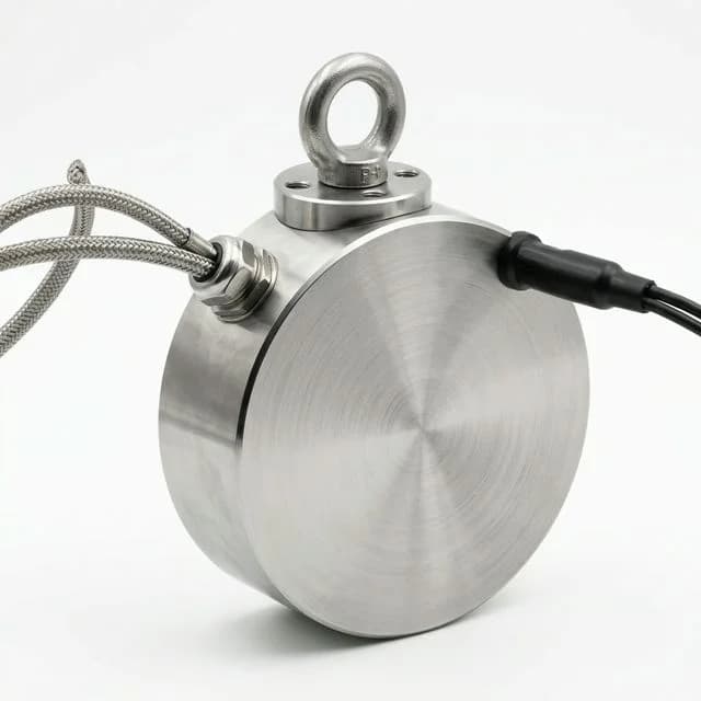
Figure 1: Product photograph of a round electromagnet. The lifting eye and housing do not establish an approved lifting capacity; this is not a calibration or proof-test record.
Ask the supplier what its rated force means. Reference plates commonly use suitable ferromagnetic steel with controlled contact and enough thickness for the particular pole geometry. However, there is no universal 15 mm plate, surface roughness, steel grade or cold-coil baseline that can safely be assumed for every catalog. Some manufacturers rate at operating temperature. Derating an already hot-rated force for heating again would count the same effect twice.
Record the reference alloy, heat treatment, plate thickness, contact coverage, flatness, surface finish, gap, supply voltage or current, and winding temperature. Also establish whether the figure is a typical breakaway result, a guaranteed minimum, or a rated working load with a defined test procedure. These quantities are different procurement commitments.
DIN VDE 0580:2011-11 addresses electromagnetic devices, operating conditions and testing. Its public scope is not evidence that every supplier used the same reference plate or that the numerical factors in an unrelated guide apply to its products.
2. Magnetic Physics: Why Small Gaps Matter
For an idealized pole interface with approximately uniform normal flux density, magnetic pressure gives:
F = B² × A / (2 × μ₀)
Here, F is normal force in newtons, B is gap flux density in teslas, A is the effective pole area in square meters, and μ₀ is approximately 1.2566 × 10⁻⁶ H/m. For multiple poles, evaluate their individual contributions; a housing diameter is not automatically the effective area. Fringing, leakage and nonuniform fields limit this simplified expression.
The square relationship is useful: if B becomes 70% of its reference value with area unchanged, the model gives 49% force retention. A 30% flux-density reduction therefore means a 51% force reduction. This is a mathematical consequence of the model, not a measured derating curve.
A simple magnetic circuit uses Φ = N × I / R_total, where Φ is flux, N is coil turns, I is current and R_total is total magnetic reluctance. For a uniform segment, R = l / (μ × A). An air gap has relative permeability close to one; ferromagnetic steel can have much higher permeability, depending on field strength and material condition.
For illustration only, if a steel path has relative permeability 2,000 and equal cross section, a 0.1 mm air segment has the same reluctance as 200 mm of that idealized steel path. Real designs may cross more than one gap and may saturate. Treat permeability as a field-dependent property, rather than a fixed alloy lookup constant. The IEC magnetic-materials vocabulary provides terminology, not product-specific force ratings.
3. Air Gap Derating: A Reproducible Sensitivity Example
The relevant separation includes coating on both mating surfaces, nonmagnetic spacers, debris, local burrs and workpiece bow. A roughness value alone does not describe the largest local gap. Measure the interface over the active poles and use the supplier's definition of gap when reading its force curve.
To illustrate sensitivity without inventing a universal supplier curve, assume fixed current, constant effective area and a linear magnetic circuit. Choose an illustrative effective gap scale h = 0.25 mm, then calculate:
k_gap = [h / (h + g_gap)]²
Here g_gap is pole-to-workpiece separation in millimeters. The chosen h absorbs reference reluctance and the number of gap crossings; it is not a measured dimension of either photographed magnet. The model ignores saturation and changing leakage. Different h values produce different curves, so these numbers must not be used as production acceptance limits.
| Gap g_gap | Calculated force retention | Calculated k_gap | What the buyer should establish |
|---|---|---|---|
| 0.00 mm | 100.0% | 1.000 | Supplier's actual reference contact condition |
| 0.05 mm | 69.4% | 0.694 | Minimum coating or spacer allowance |
| 0.10 mm | 51.0% | 0.510 | Total coating on both mating faces |
| 0.20 mm | 30.9% | 0.309 | Coating plus flatness and contamination allowance |
| 0.35 mm | 17.4% | 0.174 | Local lift-off from burrs or part bow |
| 0.50 mm | 11.1% | 0.111 | Whether the magnet is intended for this stand-off |
| 1.00 mm | 4.0% | 0.040 | Application-specific force data before selection |
Diagram 1: Illustrative Air Gap Sensitivity
The points below use the same equation and assumptions as the table. They are calculated examples, not measured manufacturer data.
4. Armature Plate Thickness and Saturation
The workpiece is part of the return path. A thin sheet can restrict flux between the center and return poles, increase local saturation and allow more leakage. Increasing plate thickness may improve force until another part of the circuit becomes limiting. It does not imply that all flux is contained or that a universal thickness ratio predicts force.
Figure 2: Construction illustration of a round electromagnet. This cutaway is not a pole-field measurement or proof of thin-sheet performance.
Critical thickness depends on pole spacing, pole area, steel properties, current and gap. Do not convert a magnet's outside diameter into a required sheet thickness with a universal percentage. Request a thickness-versus-force curve for the proposed model. A sufficiently thick reference plate for one magnet may still be inadequate for another.
| Workpiece condition | Main concern | Evidence to request |
|---|---|---|
| Thick flat reference plate | Whether the reference rating is reproducible | Plate drawing, alloy and rated-force test method |
| Minimum production sheet gauge | Restricted magnetic return section | Force test at minimum permitted thickness |
| Large unsupported sheet | Bending creates local separation | Test with production supports and grip spacing |
| Holes or cutouts over poles | Reduced overlap and return path | Part drawing overlaid on pole layout |
| Narrow strip across a round face | Only part of the active pole area is covered | Force data for the actual strip width and position |
| Multiple stacked sheets | Interlayer gaps and unequal pickup | Tests for the complete stack and required sheet count |
Diagram 2: Thick and Thin Return Paths
This qualitative schematic explains the return-path issue. Dimensions, field lines and force are not to scale.
5. Material Permeability and Alloy Selection
The exact grade and its manufacturing history matter. Heat treatment, cold work and residual stress can change magnetic behavior. A grade name alone cannot supply a reliable relative permeability or force multiplier at the operating field. Ask for a relevant B-H curve when modeling, then validate the assembled interface.
The following table identifies selection questions, rather than assigning unsupported universal percentages:
| Material family | Selection consideration | Procurement action |
|---|---|---|
| Low-carbon steel, such as 1018 | Common reference candidate; condition still matters | Match the supplier reference grade and treatment |
| Structural steel, such as S235 or A36 | Surface scale and batch condition can affect contact | Test representative production material |
| Medium-carbon steel, such as 1045 | Magnetic behavior changes with treatment | Declare hardness and heat treatment |
| Alloy steel, such as 4140 | Tempered condition differs from annealed stock | Supply condition-specific samples |
| Hardened tool steel | Retention and residual sticking both need evaluation | Include pull and release tests |
| Gray cast iron | Graphite and surface condition affect the return path | Use actual castings for qualification |
| Ferritic or martensitic stainless | Magnetic response does not imply mild-steel capacity | Verify exact grade and processing condition |
| Annealed austenitic 304 or 316 | Generally unsuitable for dependable magnetic holding | Consider another gripping method or a designed steel armature |
Cold-worked austenitic stainless may respond to a hand magnet. That observation cannot establish production holding force. If incoming material condition varies, the acceptance plan must cover the weakest permitted condition, rather than the most magnetic sample available.
6. Surface Roughness and Hot-Coil Force
Surface Finish: Avoid Counting One Gap Twice
Surface peaks, waviness and coatings influence the actual magnetic interface. Ra is an average profile statistic; it cannot be converted directly into a uniform air gap or a universal roughness multiplier. Two surfaces with the same Ra can have different flatness, machining direction and contact coverage.
If the supplier's application force curve already uses your coated, rough production plate, do not add separate generic paint and roughness penalties. If the curve uses a ground reference, request a comparison on the production finish. Removing a coating may improve magnetic contact but also changes corrosion protection and the part specification; agree that trade-off before procurement.
Thermal Resistance: Current Retention Is Not Force Retention
For a copper winding, a useful approximation near the reference temperature is:
R(T) = R20 × [1 + α × (T − 20°C)]
Use the supplier's winding coefficient where available. The calculation here assumes α = 0.00393 per °C. Texas Instruments TIDU578, section 1.2 explains the same resistance-rise mechanism and the distinction between voltage and current drive; its design uses a slightly different copper coefficient, 0.00404 per °C. Neither coefficient establishes the force rating of a holding magnet.
For an illustrative 24 V coil with R20 = 24 ohms, initial current is 1.00 A. At a winding temperature of 95°C, the assumed 75°C rise gives R_hot = 31.074 ohms, I_hot = 0.772 A and electrical power of approximately 18.54 W under fixed voltage.
In a linear, unsaturated circuit with unchanged geometry, B is proportional to I, so k_temp ≈ (I_hot / I_cold)² = 0.597. Thus a 22.8% current reduction corresponds to approximately 40.3% force reduction in this model. It would be incorrect to call 77.2% current retention 77.2% force retention. Saturation, changing material properties and regulated-current drive change the result; measure hot-state force rather than applying 0.597 universally.
Winding temperature is not housing temperature. Record how temperature was established and whether steady state was reached. A 100% duty rating applies only within specified voltage, mounting and ambient conditions. An insulation class by itself does not authorize a particular continuous operating temperature or guarantee force. If the catalog force is already hot-rated at the same conditions, do not apply a second heating reduction.
Need comparable supplier data? Send the reference and production conditions with your application review request, and ask for both cold and stabilized hot results using the same workpiece.
7. Shear Loading, Peeling and Acceleration
Axial breakaway force acts perpendicular to the face. A vertical plate also needs resistance to sliding. A simple static-friction model gives F_shear ≤ μ × F_normal, where μ must represent the actual interface. Oil, coatings, vibration and surface wear can change it. A catalog axial pull test does not measure μ.
For illustration, a 20 kg vertical plate weighs 196.2 N. If μ is assumed to be 0.15, static equilibrium alone requires F_normal ≥ 196.2 / 0.15 = 1,308 N. That number excludes acceleration, design margin and any peeling moment. The assumed coefficient is not a certified steel-on-steel property.
Mechanical stops or pockets can carry shear, but their fasteners, bearing area and supporting structure need their own load calculation. A friction pad may improve sliding resistance while adding a magnetic gap; compare the complete assembly. Where the center of gravity is offset, calculate moments and how individual magnets unload. Multiple magnets do not automatically share load equally on a flexible sheet.
8. Preliminary Sizing and a Worked Procurement Example
For a pure axial load with vertical acceleration aligned against gravity, a screening calculation is:
F_catalog_required ≥ m × (g₀ + a_z) × S / K_application
Here m is workpiece mass, g₀ = 9.81 m/s², a_z is the upward acceleration magnitude for this case, S is an application design margin and K_application is retained force relative to the chosen catalog reference. Use a separate directional load and moment analysis for other motions, including emergency stops. Do not add a general acceleration vector to gravity as if every component acted axially.
K_application should come from supplier data or testing of the combined plate, gap, finish, current and temperature conditions. Multiplying independently guessed gap, roughness, material and thickness factors can count the same loss twice and miss interactions. It is neither a verified safety bound nor a substitute for a combined-condition test. Changing magnet size also changes the magnetic circuit, so a ratio measured for one model cannot automatically be transferred to another.
Standards boundary: ASME B30.20 addresses below-the-hook lifting devices and related requirements. It does not establish a single 2:1 or 3:1 rule for every robotic gripper, workholding fixture or collaborative application. The responsible designer must identify the applicable equipment standard, edition, design requirements, tests and local rules. The margin below is only an arithmetic assumption.
Hypothetical Gantry Selection
Assume a 400 × 400 × 2.5 mm steel plate and an illustrative density of 7,850 kg/m³. Its calculated mass is 0.4 × 0.4 × 0.0025 × 7,850 = 3.14 kg. Actual drawings and tolerances should determine the production mass.
Assume an upward acceleration of 11.8 m/s², an illustrative margin S = 2.5, and a placeholder combined retention K_application = 0.15. The last two values are not taken from a standard or measured on a product. They demonstrate what the buyer must replace with approved requirements and test evidence.
- Dynamic axial demand:
3.14 × (9.81 + 11.8) = 67.86 N. - Demand including the assumed margin:
67.8554 × 2.5 = 169.64 N. - Indicative catalog force:
169.6385 / 0.15 ≈ 1,131 N.
Sensitivity is more useful than the isolated number: if verified retention were 0.10, the same arithmetic would require approximately 1,696 N; at 0.25 it would require approximately 679 N. This is why an unverified retention factor cannot authorize a purchase or a payload rating.
The procurement decision is to obtain combined-condition data for candidate magnets, rather than order any unit marked 1,131 N. A different pole layout, distributed gripping points or a mechanical support may be preferable to a larger magnet. Account for supply tolerance, wiring voltage drop, power-loss behavior and release requirements before approving the assembly.
9. Procurement Checklist and Acceptance Method
Attach these items to the RFQ so suppliers quote the same operating case:
- Workpiece: Drawing, mass tolerance, alloy, heat treatment and minimum thickness.
- Contact: Pole coverage, holes, edge location, flatness, coating on both faces and maximum gap.
- Surface condition: Roughness, scale, oil, debris and permitted wear over service life.
- Electrical supply: Coil voltage or regulated current, tolerances, cable length and driver behavior.
- Thermal conditions: Ambient, mounting heat path, duty cycle and stabilized winding temperature.
- Loads: Axial demand, shear, moments, acceleration, emergency stopping and load sharing.
- Release and loss of power: Allowed release time, residual sticking, suppression circuit and required retention strategy.
- Evidence: Guaranteed application force, reference plate details, test method, uncertainty, repeat count and applicable equipment requirements.
A useful acceptance method begins by fixing the candidate part number and documenting a reference pull test. Use a calibrated load cell and an aligned fixture so the measurement is axial, not an accidental peel test. State the pull direction and rate, the plate drawing and the supply measured at the coil terminals.
Next, test representative production parts at the minimum thickness, maximum permitted gap, weakest material condition and stabilized hot state. Record temperature, current, force and failure mode. Include tolerances and contamination that are allowed in service. A single favorable sample cannot define the minimum production force; agree sample size, repetitions and acceptance thresholds with the responsible engineer.
Then evaluate shear and moments in their actual directions. Check the complete motion cycle, stopping case, release delay and required power-loss response in a controlled fixture. Record whether the failure was sliding, axial separation, sheet bending or incomplete release, because the corrective design differs for each mode. Product photos and magnetic simulation may support discussion, but they do not replace these test records.
Finally, keep the tested configuration tied to the purchase specification. Changes in workpiece coating, steel condition, driver current, pole geometry or magnet spacing should trigger review. Recheck this guide when a cited standard changes; requalify the application whenever its approved operating envelope changes.
10. Frequently Asked Questions
How much does a standard layer of paint reduce holding electromagnet force?
There is no universal percentage. Measure the maximum pole-to-workpiece separation, including coating on both mating faces, and use the selected magnet’s force-versus-gap curve at the relevant current and plate condition. The illustrative curve in this guide is a calculation model, not a product rating.
Can we stack multiple thin steel sheets to prevent magnetic saturation?
Do not treat a stack as a solid armature of equal total thickness. Interlayer gaps and uneven contact alter the magnetic path, and individual sheets may slip or remain behind. Validate the complete stack and each required pickup condition; a single-sheet test cannot establish stack capacity.
Why does our holding electromagnet become hot and lose strength after 30 minutes of continuous operation?
Copper resistance rises as the winding heats. At fixed voltage, a 75°C rise gives approximately 29.5% higher resistance and 22.8% lower current using a copper coefficient of 0.00393 per °C. An unsaturated fixed-geometry model predicts about 59.7% force retention. Actual force and warm-up time require hot-state testing; regulated-current operation behaves differently.
What is the difference between breakaway force and shear holding force in robotic end-effectors?
Breakaway force acts perpendicular to the pole face. Sliding resistance depends on normal clamping force and the actual interface friction, with F_shear approximately equal to mu times F_normal in a simple friction model. Coating, oil, vibration and peeling moments require separate evaluation; mechanical stops also need their own load rating.
Can holding electromagnets be used to clamp stainless steel workpieces?
Annealed austenitic 304 and 316 are generally unsuitable for dependable magnetic holding. Cold work can alter their response, while ferritic and martensitic stainless grades are magnetic. None of these labels establishes a force multiplier: test the exact grade, heat treatment, thickness and surface condition.
How do we reduce residual sticking when the electromagnet is de-energized?
Options include low-remanence materials, a mechanical ejector, an anti-stick spacer, or a supplier-approved demagnetizing waveform. A spacer reduces energized holding force, and excessive reverse current can re-magnetize the circuit. Verify release time with the actual driver, suppression circuit and workpiece; no option guarantees complete release in every condition.
11. Sources, Standards and Verification References
The following references support terminology, standard scope and coil-drive behavior. Public catalog records do not provide all normative clauses. No linked standard supplies the illustrative air-gap curve, placeholder retention ratio or example design margin used here.
- DIN VDE 0580:2011-11 — Electromagnetic devices and components, general specifications. Publisher record and scope for electromagnetic devices, operating conditions and tests; obtain the applicable edition for normative requirements.
- ASME B30.20-2025 — Below-the-Hook Lifting Devices, ANSI publisher listing. Equipment-standard scope for marking, construction, inspection, testing and operation; not a universal robot-gripper safety-factor table.
- IEC Electropedia, Part 221 — Magnetic materials and components. Vocabulary reference for magnetic quantities. Definitions do not establish numerical material multipliers.
- Texas Instruments TIDU578 — Current Controlled Driver for 24-V DC Solenoid With Plunger Fault Detection, section 1.2, printed page 4. Explains winding resistance rise and voltage-versus-current drive. Its moving-solenoid design does not establish holding-magnet payload capacity or a safe reduced holding current.
12. Turn the Derating Review into a Comparable RFQ
Start with the actual workpiece and load case. For thin sheet, ask whether alternative pole spacing or distributed magnets will improve the return path without bending the part. For a coated plate, ask for force at maximum allowed stand-off. For continuous operation, ask for stabilized hot-state results at the minimum supply condition.
Send your workpiece drawing and operating requirements to discuss candidate holding electromagnets and request a quotation with its force reference conditions stated. Include the checklist above so the proposed model, test evidence and remaining validation work are explicit before purchase.
Autor

Categorías
Más artículos
IP67 vs IP69K Waterproof Electromagnets: 2026 Procurement Guide to Coil Potting
Specify waterproof electromagnets for 2026 RFQs: compare IP67 vs IP69K, potting compounds, validation tests, cost tradeoffs, and supplier proof.


Electromagnet & Solenoid Market Update (2026-W16): NOES and 232
Decision update for OEM buyers: April 2026 NOES and Section 232 changes, EU GOES timeline, and the exact RFQ fields to update before the next PO cycle.
Proportional Solenoid vs. On/Off Solenoid: Force-Stroke Linearity, PWM Dither, and Hysteresis Guide
Compare proportional solenoid vs on/off solenoid behavior, force-stroke curves, dither and hysteresis. Use the RFQ checklist to review your actuator design.