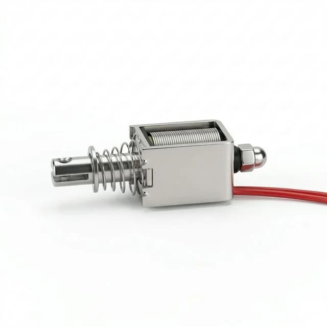
Electromagnetic Coil Duty Cycle (ED): The 2026 Thermal Management Guide for OEM Procurement
Specify solenoid duty cycles (ED%) to prevent thermal burnout. Learn VDE 0580, I²R heating, insulation classes, and hit-and-hold driver options for OEM buyers.
One-Line Decision: Specifying the correct Duty Cycle (Relative Duty Factor, ED) prevents the #1 cause of solenoid failure in the field: catastrophic thermal burnout due to I²R resistive heating.
Need immediate engineering support for a thermal failure issue? Contact our engineering team to review your duty-cycle requirements, ambient temperature constraints, and driver circuitry for a custom electromagnet.
Published / updated: 2026-07-19. Scope: Buyer and engineer specification guide for electromagnetic coil duty cycles (ED), thermal management, and failure prevention in industrial automation, medical devices, and robotics. Not covered: High-voltage transformer winding calculations, permanent magnet demagnetization curves.
The Hidden Cost of Thermal Failure in OEM Machinery
In the landscape of industrial automation and OEM machinery procurement for 2026, the humble electromagnet—whether serving as a linear solenoid actuator, a holding magnet for a robotic end effector (EOAT), or a locking mechanism—remains a critical point of failure. Despite being structurally simple devices consisting of copper wire wound around a steel bobbin, they are frequently mis-specified during the procurement phase.
The most common, and most expensive, error is ignoring the Duty Cycle (ED).
When a procurement team purchases an off-the-shelf electromagnet without perfectly aligning its ED rating with the machine's actual operational rhythm, the result is almost always thermal failure. Thermal failure does not mean the magnet simply stops working gracefully; it means the internal copper windings heat up until their enamel insulation boils, cracks, and short-circuits. This thermal runaway can melt surrounding plastic housings, fry expensive control boards, and cause unplanned production line downtime that costs thousands of dollars per minute.
Understanding and specifying the correct duty cycle is not merely a technical box to check; it is a fundamental requirement for Total Cost of Ownership (TCO) optimization.
Defining Duty Cycle: The Physics of I²R Heating
To understand why duty cycles exist, buyers must understand the basic physics of an electromagnetic coil.
When an electrical current ($I$) flows through the copper wire of a solenoid, the inherent electrical resistance ($R$) of the copper causes a portion of that electrical energy to be converted directly into heat. This is known as Joule heating or I²R losses.
As long as the electromagnet is energized, it is actively generating heat. The coil relies on the surrounding environment—the ambient air, the metal chassis it is bolted to, or its potting compound—to dissipate this heat.
- If the rate of heat generation is less than or equal to the rate of heat dissipation, the coil reaches a stable "steady-state" temperature and operates safely indefinitely.
- If the rate of heat generation exceeds the rate of heat dissipation, the temperature of the coil climbs continuously until the internal insulation melts and the device is destroyed.
The Relative Duty Factor (ED) Formula
Under European standards such as DIN VDE 0580, the duty cycle is formally referred to as the Relative Duty Factor (ED - Einschaltdauer). It is expressed as a percentage and is calculated by comparing the time the magnet is turned ON against the total cycle time (ON time + OFF time).
Formula:
ED% = [ ON Time / (ON Time + OFF Time) ] × 100
For example, if a solenoid actuator is energized for 2 seconds to push a diverter gate, and then rests (de-energized) for 8 seconds before the next part arrives, the calculation is:
[ 2 / (2 + 8) ] × 100 = 20% ED.
This mathematical relationship ensures that the coil is given enough time in a zero-current state (No-Current Break, NCB) to shed the heat it accumulated during the switch-on period.
Visualizing the Duty Cycle & Heat Accumulation
The graph above demonstrates how an intermittent duty cycle allows the internal temperature of the coil to stabilize below the critical thermal limit. If the "OFF" times were removed (100% ED operation on a 25% coil), the orange temperature curve would rapidly breach the red thermal limit.
The 4 Standard Duty Cycle Classes: A Procurement Comparison
In industrial procurement, solenoids are generally categorized into four distinct duty cycle classes. Attempting to cross-apply these without engineering adjustments guarantees failure.
For the exact same physical size (volume of copper and steel), a lower duty cycle coil is wound with thicker wire and lower resistance. This allows a massive surge of current to generate extreme pulling force, but limits its ON time to mere seconds. Conversely, a 100% ED coil has higher resistance, draws minimal current, produces less pulling force, but can stay ON forever.
| Duty Cycle Class | ED % Rating | Max "ON" Time | Relative Pulling Force | Thermal Dissipation | Failure Risk & Buyer Decision Point | Supplier Communication Field |
|---|---|---|---|---|---|---|
| Continuous Duty | 100% ED | Infinite (∞) | 1.0x (Baseline lowest) | Low (Reaches steady-state) | Over-speccing size/cost. Use when hold is permanent. | Ask for steady-state Temp Rise (ΔT) at 100% ED. |
| Heavy Intermittent | 50% ED | ~5 to 10 minutes | 1.4x to 1.5x | Moderate | Conveyor jams can cause 100% ED and thermal burnout. | Specify max jam time (worst-case ON time). |
| Standard Interm. | 25% ED | ~1 to 2 minutes | 2.0x | High (Needs exact off-time) | Insufficient cooling time between fast cycles. | Provide expected cycle rate (cycles per minute). |
| Short Time Duty | 10% ED | ~10 to 30 seconds | 3.0x | Very High | Controller failure leaves it ON, melting in seconds. | Ask if thermal fuse/PTC is available internally. |
| Impulse Duty | 5% ED | Milliseconds to 5s | 4.0x | Extreme (Instant heat) | Mechanical shock from extreme force damages stop. | Request impact dampening or hardened plungers. |
| Latching (Bistable) | 0% ED | Milliseconds (Switch) | Variable | Zero (During hold) | Demagnetization due to reverse polarity errors. | Specify permanent magnet grade (NdFeB/SmCo). |
Note: The "Max ON Time" is governed by the VDE 0580 operational cycle time constraints. An electromagnet cannot stay ON for an hour just because it will be turned OFF for 9 hours, even if that mathematically equals a 10% ED. Absolute time limits apply.
Ambient Temperature & Thermal Insulation Classes (B, F, H)
Procurement engineers must remember that duty cycle ratings are rarely absolute; they are inextricably linked to the ambient environment.
Standard ED specifications provided by manufacturers are typically calibrated for an ambient air temperature of 20°C (68°F) or 35°C (95°F), assuming the solenoid is mounted to a thermally conductive steel plate (heat sink).
If your machinery operates in a foundry at 60°C, or inside a sealed NEMA 4X / IP67 robotics enclosure where internal temperatures reach 75°C, your thermal budget is severely compromised. A solenoid rated for 100% ED at 20°C may only be capable of 40% ED at 70°C before its insulation breaks down.
To combat this, buyers must specify the correct Insulation Class:
- Class B (130°C Limit): Standard for indoor, climate-controlled automation.
- Class F (155°C Limit): The standard upgrade for rugged industrial machinery and mobile robotics.
- Class H (180°C Limit): Reserved for extreme environments (automotive under-hood, aerospace, high-density sealed enclosures).
"Hit and Hold" Circuits: The 2026 Strategy to Beat Duty Cycle Constraints
Historically, engineers faced a painful compromise: if they needed massive pulling force (which requires a 10% ED coil) but also needed to hold that payload indefinitely (which requires a 100% ED coil), they had to buy an unnecessarily massive, heavy, and expensive solenoid that was naturally strong enough at 100% ED.
In 2026, smart factories utilize "Hit and Hold" (Pick and Hold) driving strategies to eliminate this compromise.
The physics of magnetism dictate that moving a plunger across an air gap (the stroke) requires a tremendous amount of energy. However, once the plunger has closed the air gap and made contact with the core, the magnetic circuit is completed. Holding the plunger in place requires only a fraction (often 15% to 25%) of the energy required to pull it.
Modern controllers use Pulse Width Modulation (PWM) or dual-voltage power supplies to exploit this:
- The Hit (Pull Phase): The controller hits the coil with 24VDC for 100 milliseconds. The massive surge of current provides the strength of a 10% ED coil, snapping the plunger shut.
- The Hold (Hold Phase): Immediately after closing, the controller rapidly pulses the voltage (PWM) to step the effective voltage down to 6VDC, or switches to a secondary low-voltage circuit.
- The Result: The coil maintains its grip indefinitely at a 100% ED thermal state without overheating, while delivering the initial pulling force of an oversized actuator.
The Engineering Procurement Checklist for Electromagnets
Before issuing a Purchase Order (PO) for an off-the-shelf or custom solenoid, procurement and engineering teams should align on this exact checklist to prevent thermal failure:
- Define the Absolute Maximum ON Time: In a worst-case scenario (e.g., a jam on the conveyor belt), what is the longest duration the controller will leave the coil energized?
- Define the Absolute Minimum OFF Time: How fast does the machine cycle? Is there guaranteed rest time before the next pulse?
- Calculate the ED%: Using the formula
(ON) / (ON + OFF) * 100. - Measure Max Ambient Temperature: What is the air temperature inside the enclosure next to the coil during peak summer production, not just the factory floor temperature?
- Verify Heat Sinking: Will the electromagnet be bolted to a heavy, thermally conductive metal chassis, or will it be suspended in air or mounted to insulating plastic? (Plastic mounting requires derating the ED).
- Select Insulation Class: Based on ambient temp + I²R rise, specify Class B, F, or H wire.
- Evaluate Driver Electronics: Can the PLC or motor controller support a PWM "Hit and Hold" circuit to artificially extend a low-ED coil into continuous holding duty?
Buyer Q&A: Real-World Procurement Questions
Q: We are upgrading a 12VDC 100% ED solenoid to get more force by supplying 24VDC. Is this safe?
A: No. Doubling the voltage quadruples the power (and heat) because $P = V^2 / R$. A 100% ED coil will instantly become a 25% ED coil thermally. If your machine still runs it continuously, it will suffer catastrophic thermal runaway and burn out in minutes.
Q: How do we mathematically verify a supplier's ED rating before mass production?
A: Request the "Temperature Rise Curve" or $\Delta T$ test data. The supplier must provide a laboratory graph showing the coil's internal temperature plateauing safely below its insulation class limit (e.g., 155°C for Class F) when run at the specified ED% under load.
Q: Our solenoids are burning out in the field during summer months, but they passed our standard lab testing. Why?
A: Lab testing is typically conducted at 20°C ambient with the solenoid mounted to a large, thermally conductive steel mass. If your field units are installed inside sealed NEMA enclosures running at 50°C ambient, or mounted on insulating plastics, thermal dissipation is severely choked. You must derate the ED% or upgrade the insulation class for real-world environmental boundaries.
If your RFQ still lacks ON/OFF timing, ambient temperature, mounting material, insulation class, or driver strategy, send the duty-cycle assumptions to engineering before releasing the PO. A short review can prevent field burnout, warranty returns, and late-stage driver redesign.
Sources and References
To ensure absolute reliability in your machine design, our engineering team relies on the following established standards and application notes:
- DIN VDE 0580 (VDE 0580):2011-11: Electromagnetic devices and components - General specifications, which governs terminology, operating conditions, safety requirements, and tests for electromagnetic devices. View VDE 0580
- Texas Instruments DRV110: A power-saving solenoid controller reference for peak-and-hold current regulation, PWM control, and reduced hold current after actuation. View DRV110
- IEC 60085:2007: Electrical insulation - Thermal evaluation and designation, establishing criteria for evaluating thermal endurance and assigning thermal classes for electrical insulating materials and systems. View IEC 60085
Autor

Categorías
Más artículos
The Shift to 48V Solenoids in AGV/AMR: 12V vs 24V vs 48V Procurement Guide
Specify 48V solenoids and electromagnets for next-gen AGV/AMR platforms. Compare 12V, 24V, and 48V architectures, thermal efficiency, wiring weight, and costs.
Electromagnet & Solenoid Market Update (2026-W16): NOES and 232
Decision update for OEM buyers: April 2026 NOES and Section 232 changes, EU GOES timeline, and the exact RFQ fields to update before the next PO cycle.
PFAS-Free Solenoids & Electromagnets: 2026 Procurement & Engineering Guide
Specify PFAS-free solenoids and electromagnets for 2026. Compare FKM/PTFE alternatives, thermal limits, compliance risks, and RFQ checklist before sourcing.