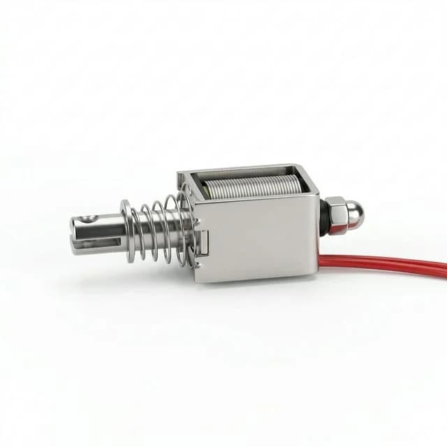
Bistable Latching Solenoids: Zero-Power Holding Guide for AGV/AMR Design
Specify bistable latching solenoids for 2026 battery-powered robotics. Compare monostable vs latching, driver circuits, thermal management, and TCO for AMRs.
One-Line Decision: If your AGV or AMR mechanism needs to hold a position for more than a few seconds, specifying a standard monostable solenoid will drain your battery and overheat the enclosure; you must specify a bistable latching solenoid to achieve zero-power holding, significantly improving robot uptime and thermal reliability.
Need immediate engineering support for an AMR locking or actuation mechanism? Contact our engineering team to review your duty-cycle, thermal constraints, and driver circuitry for a custom electromagnet.
Published / updated: 2026-06-24. Scope: Buyer and engineer specification guide for latching (bistable) solenoids used globally in Automated Guided Vehicles (AGVs), Autonomous Mobile Robots (AMRs), battery-powered locks, and aerospace actuators. Not covered: AC-driven industrial solenoids, proportional control valves, and high-voltage grid switchgear.
The Core Challenge: I²R Heating in Battery-Powered AMRs
As mobile robotics density increases in 2026, engineering teams are fighting for every watt-hour of battery life. A standard continuous-duty (100% ED) monostable solenoid draws constant electrical current just to hold a mechanical position. Whether it is keeping a laser scanner shutter open, a payload locked in place, or a parking brake disengaged, that continuous draw behaves like a parasitic drain on the system.
This continuous current creates I²R losses (heat). Inside the tightly packed, sealed enclosures of IP67-rated AMRs, this heat cannot easily escape. It elevates the ambient temperature of the robot's interior, degrading nearby sensitive control electronics, accelerating battery degradation, and drastically reducing the overall operational uptime of the robot. Engineers often find themselves adding forced-air cooling fans or heavy aluminum heatsinks just to manage the thermal output of a simple holding actuator.
The Solution: The bistable latching solenoid fundamentally changes this dynamic. It operates on a completely different electromagnetic paradigm. Instead of relying on a continuous electromagnetic field to hold an armature, it uses a short electrical pulse (typically 50–100 milliseconds) to move the plunger. Once moved, an internal permanent magnet takes over, holding the plunger in place with zero continuous power. To release the mechanism, a reverse-polarity electrical pulse is sent through the coil, temporarily canceling the permanent magnet's field and allowing a return spring to push the plunger back to its original position.
This means that whether the robot needs to hold a payload lock for ten seconds or ten hours, the energy consumed by the actuator is identical: just two tiny millisecond pulses.
Monostable vs. Bistable (Latching): 2026 Procurement Comparison
When deciding between a standard (monostable) solenoid and a latching (bistable) solenoid, procurement and engineering teams must evaluate both the thermal envelope, control complexity, and the overarching system cost.
| Feature / Metric | Standard (Monostable) Solenoid | Latching (Bistable) Solenoid |
|---|---|---|
| Power Consumption (Holding) | Continuous (High, relative to holding force) | Zero (Only consumes power during transition) |
| Thermal Dissipation (Heat) | High (Requires ventilation, heatsinking, or potting) | Negligible (Runs cold during hold phase) |
| Fail-Safe Behavior | Returns to default state on power loss (Fail-Open/Closed) | Remains in last state on power loss (Fail-in-Place) |
| Control Circuitry Required | Simple ON/OFF relay, transistor, or MOSFET | H-Bridge (polarity reversal) or Dual-Coil driver |
| Cycle Life / Stroke Speed | Extremely fast, typically rated for millions of cycles | Fast, but magnetic flux cancellation requires precise timing |
| Component Unit Cost | Lower (Simple copper winding and steel core) | Higher (Includes Neodymium or Samarium Cobalt magnets) |
| System-Level TCO | High (Requires larger batteries and thermal management) | Low (Enables smaller batteries and sealed enclosures) |
| Best Used For | Short bursts, rapid sorting, fail-to-safe safety brakes | Battery-powered locks, long-duration hold, payload latching |
Visualizing the Latching Mechanism (Magnetic Flux Path)
Understanding why the driver circuit is more complex requires visualizing the internal magnetic pathways. Below is a simplified structural diagram of how a single-coil latching solenoid operates, utilizing a permanent magnet combined with a bidirectional electromagnetic field.
Visual Explanation: In State 1, the permanent magnet (PM) provides enough continuous magnetic flux to overcome the return spring and hold the plunger against the pole piece. No electricity is flowing. In State 2, the control circuitry fires a reverse-polarity pulse into the copper coil. This creates an opposing electromagnetic field that temporarily cancels the PM's flux, allowing the internal spring to push the plunger away. Once the plunger has moved past the PM's effective reach, the electrical pulse is shut off.
Engineering Specification & Quality Assurance Checklist
When sourcing latching solenoids for an AMR, AGV, or remote robotic platform, you must validate significantly more parameters than you would for a standard "dumb" electromagnet. The interaction between your control board, the mechanical vibration, and the permanent magnet's thermal limits requires strict oversight.
Use this checklist during your RFQ process and vendor qualification:
- Coil Type Architecture Selection: Specify whether your design requires a Single-Coil (two wires; requires an H-bridge on the PCB to reverse polarity) or a Dual-Coil (three wires; uses a common ground with separate forward/reverse inputs). Single-coil units are physically smaller and lighter, while dual-coil units simplify the external driving circuitry at the expense of actuator volume.
- Precise Pulse Duration Validation: Ensure your robotic control board (PLC or custom microcontroller) can deliver the exact millisecond pulse required by the manufacturer's datasheet. A pulse that is too long will re-attract the plunger electromagnetically (effectively bouncing the latch); a pulse that is too short won't fully cancel the permanent magnet, resulting in a jammed mechanism.
- Dynamic Vibration & Shock Ratings: Verify that the permanent magnet's baseline holding force significantly exceeds the maximum shock rating of your AMR chassis. AMRs navigating rough factory floors, docking ramps, or door thresholds experience high G-forces. If the shock exceeds the magnetic hold threshold, the load will drop unexpectedly.
- Thermal Limits of Permanent Magnets (Curie Temperature): Ensure the maximum operating environment (plus any residual heat from the brief actuation pulses) does not exceed the thermal limits of the internal magnet. Standard Neodymium (NdFeB) magnets can permanently lose their magnetic strength if exposed to temperatures above 80°C. If your AMR operates in a hot environment, you must explicitly specify high-temperature magnet grades (like Samarium Cobalt or high-temp Neodymium).
- System-Level Fail-State Safety Review: Document exactly what must happen mechanically if the robot loses battery power entirely. If a specific mechanism—such as a parking brake or a safety shutter—must mechanically engage or drop upon power loss to meet ISO safety compliance, a bistable solenoid is the wrong choice. In those critical safety pathways, you must use a spring-applied, power-released monostable electromagnet.
- Mechanical Detent Integration: For ultra-high vibration applications where dropping the latch is catastrophic, evaluate whether the bistable solenoid should drive a secondary mechanical toggle or over-center detent rather than holding the load directly with its magnetic face.
Advanced Specification Dimensions & Applicability Boundaries
While latching solenoids solve critical thermal and power issues, their applicability boundaries must be strictly respected. Understanding these boundaries prevents costly redesigns late in the prototyping phase.
Applicability Boundaries
- High-Frequency Actuation: If your mechanism actuates more than 10 times per second continuously, the repeated unlatch pulses can generate heat that rivals a monostable solenoid. Bistable units are strictly for "hold-dominant" duty cycles.
- Fail-Safe Safety Systems: As noted in ISO 3691-4 compliance reviews, bistable actuators are fail-in-place. They are forbidden in primary safety loops (like emergency E-stops or dead-man braking mechanisms) where a total power loss must result in an immediate mechanical safe state.
- Dust and Ferrous Debris Environments: The permanent magnet is always active. In environments with metal dust (e.g., CNC machine shops), ferrous particles will be continuously drawn into the plunger gap, eventually jamming the mechanism unless an IP67-rated boot or sealed housing is employed.
Critical Specification Dimensions
When moving from standard solenoids to latching variants, engineers must define several new specification dimensions:
- Minimum Latch Voltage: The voltage required to overcome the internal spring and successfully engage the permanent magnet.
- Release Voltage Window: The narrow voltage band required to accurately cancel the magnetic flux without causing a "re-latch" effect.
- Operating Pulse Duration (ms): The exact duration (typically 20–100ms) the driver circuit must maintain the current to ensure full transition without wasting energy.
- Holding Force at 20°C vs 80°C: Permanent magnets exhibit weaker magnetic flux at elevated temperatures. The holding force must be specified at the maximum expected ambient temperature inside the AMR enclosure.
Buyer Decision Points & Supplier Communication Fields
For procurement teams, sourcing a bistable solenoid requires shifting from a commodity-buying mindset to an engineered-component mindset. The buyer decision points go beyond simple unit cost and lead time; they involve total system integration.
Buyer Decision Points
- Driver Circuit Availability: Does the engineering team have the real estate and budget to implement an H-bridge motor driver, or must a bulkier dual-coil solenoid be sourced to simplify the PCB?
- Battery Payload Trade-offs: Can the higher unit cost of the bistable solenoid be offset by reducing the Li-ion battery pack size by 500Wh? In almost all AMR applications, the answer is yes.
- Custom vs. Off-the-Shelf: Standard catalogs often feature solenoids optimized for 20°C office environments (e.g., electronic door locks). AMR applications frequently require custom-wound coils for non-standard voltages (e.g., 48VDC) and high-temp magnets.
Essential Supplier Communication Fields
When generating an RFQ (Request for Quote) for a solenoid manufacturer, explicitly include these communication fields to avoid receiving inappropriate commodity parts:
- Target Application: "AMR Payload Latch" or "AGV Battery Lock"
- Duty Cycle Description: e.g., "Actuate once per hour, hold for 59 minutes."
- Available System Voltage (Max/Min): e.g., "48VDC nominal, drops to 41VDC under heavy motor load."
- Maximum Ambient Temperature: e.g., "65°C inside sealed chassis."
- Expected Shock/Vibration (G-Force): e.g., "5G intermittent shock during threshold crossing."
- Failure Mode Requirement: "Must fail-in-place. No fail-safe spring return required."
If these fields are still unresolved, pause the RFQ and send the duty-cycle and fail-state notes to engineering. A short review before quotation is cheaper than redesigning the driver board after prototype testing.
Driver Circuitry: The Hidden Engineering Complexity
A common and costly trap for procurement teams and junior engineers is treating a latching solenoid exactly like a standard relay component on the bill of materials. Because you must physically reverse the direction of the electrical current to unlatch a single-coil unit, you absolutely cannot use a simple N-channel MOSFET or a basic relay to control it.
Your electrical engineering team must integrate an H-Bridge driver IC (similar to the controllers used for bi-directional DC motors). While this adds a minor layer of complexity and a slight cost increase to the PCB level, the ROI is massive. The reduction in battery capacity requirements, the elimination of heavy heatsinks, and the ability to use fully sealed IP67/IP69K enclosures without thermal runaway quickly offsets the driver cost in any serious TCO model for mobile robotics. Furthermore, modern integrated H-bridge ICs are incredibly compact and offer built-in fault protection, making implementation far easier than it was a decade ago.
Total Cost of Ownership (TCO) in Battery-Powered Applications
When a purchasing department looks strictly at component unit costs, a bistable solenoid will always appear more expensive than its monostable counterpart. The addition of rare-earth permanent magnets and precision machining guarantees a higher baseline price.
However, in the context of 2026 AMR engineering, the unit cost is the least important metric. The true value lies in the Total Cost of Ownership (TCO) and system-level optimization:
- Battery Downsizing: If an AMR has four latching mechanisms that previously drew 10 watts each continuously for a 12-hour shift, switching to bistable solenoids saves 480 watt-hours of battery capacity. This allows you to spec a smaller, lighter, and cheaper lithium-ion battery pack.
- Thermal Management Elimination: By removing 40 watts of continuous parasitic heat from a sealed enclosure, engineers can eliminate forced-air fans, ventilation louvers, and heavy aluminum heatsinks. This reduces weight, lowers manufacturing complexity, and drastically improves the IP rating of the vehicle.
- Increased Mission Uptime: Less power drawn by parasitic actuators means more power dedicated to the drive motors. The robot can spend more time on the factory floor moving payloads and less time sitting idle at a charging station.
- Component Longevity: Because the coil only experiences current for a fraction of a second, the internal copper windings run extremely cool. The risk of thermal degradation to the coil insulation is virtually eliminated, resulting in a significantly longer operational lifespan compared to continuous-duty coils operating near their thermal limits.
Frequently Asked Questions (FAQ)
Q: Do latching solenoids consume any power while holding?
A: No. Once the internal permanent magnet engages the armature, it holds position indefinitely with zero electrical current and zero I²R heat generation. This makes them ideal for battery-constrained environments where energy conservation translates to extended uptime.
Q: What happens to a bistable solenoid if the AMR loses complete battery power?
A: It fails in place. Unlike a standard monostable solenoid (which relies on an internal return spring to snap back to a default position when power drops), a latching solenoid remains in its last actuated state until a reverse-polarity pulse is deliberately applied. If safety requires a fail-open or fail-closed state upon total power loss (like a safety brake), a bistable solenoid may not meet regulatory compliance.
Q: Why does our latching solenoid drop the load under heavy vibration?
A: The holding force of the internal permanent magnet must exceed the shock and vibration G-forces transmitted through the AMR chassis. If a bump on the factory floor creates a momentary force that exceeds the magnetic hold threshold, the armature will detach. Specifying a higher-grade rare-earth permanent magnet or designing a mechanical detent into your linkage is absolutely required for high-vibration terrain.
Q: Can we drive a latching solenoid with a standard relay?
A: Usually not efficiently. You need to reverse the current polarity to unlatch. This requires either a dual-coil design (which uses simple switching but is bulkier) or an H-bridge motor driver to flip the polarity on a smaller single-coil design.
Q: Are latching solenoids more expensive than standard solenoids?
A: Yes, the initial component cost is higher due to the inclusion of rare-earth permanent magnets and often more complex magnetic circuits. However, the Total Cost of Ownership (TCO) is lower in mobile robotics because they reduce battery capacity requirements, eliminate the need for active cooling, and extend mission uptime.
Q: How critical is the pulse duration for unlatching?
A: Extremely critical. The controller must send a precise millisecond pulse. A pulse that is too long will essentially turn the solenoid into an electromagnet with the opposite polarity, causing it to push away and then immediately re-attract the plunger. A pulse that is too short will fail to completely cancel the permanent magnet’s flux, causing it to remain latched.
Sources, Standards, and Verification References
To validate the engineering principles of zero-power holding, electromagnetic flux cancellation, and thermal management in mobile robotics, refer to these verifiable industry resources:
- Texas Instruments: Driving Solenoids and Relays with DRV8x Motor Drivers (Application Note SLVAEM4) - Details on using H-bridge drivers for bidirectional DC inductive loads like single-coil latching solenoids.
- ISO 3691-4:2020 Industrial trucks — Safety requirements and verification - Covers regulatory compliance for driverless industrial trucks (AGVs/AMRs), essential when evaluating fail-in-place vs. fail-safe behaviors.
- K&J Magnetics: Temperature and Neodymium Magnets - Practical engineering reference for NdFeB temperature grades, reversible loss, and irreversible strength loss at elevated temperature.
Ready to Optimize Your AMR Actuators?
Moving to a bistable latching architecture is one of the most effective ways to save watts of power, extend battery runtimes by hours, and permanently solve your enclosure overheating issues. If you are designing the next generation of Automated Guided Vehicles, don't let outdated continuous-duty actuators artificially limit your performance.
Contact our engineering team to discuss your specific pulse constraints, holding force requirements, vibration environments, and driver circuit compatibility today. We specialize in custom winding and magnetic circuit optimization for high-performance robotics.
Author

Categories
More Posts
Q3 2026 Sourcing Alert: How New Copper & NOES Tariffs Impact Electromagnet Costs
Q3 2026 copper and NOES tariff changes affect electromagnet, solenoid, clutch, and holding magnet RFQs. Review cost, lead-time, and spec actions.
Electromagnet & Solenoid Update (2026-W18): HTS Buyer Gates
OEM buyer update for April 29, 2026: HTS technical corrections, exposed electromagnet/solenoid sourcing paths, and this week's RFQ + customs control gates.
PFAS-Free Solenoids & Electromagnets: 2026 Procurement & Engineering Guide
Specify PFAS-free solenoids and electromagnets for 2026. Compare FKM/PTFE alternatives, thermal limits, compliance risks, and RFQ checklist before sourcing.